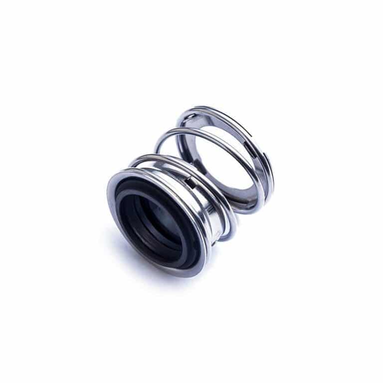
La principale différence entre un joint tandem et un joint double réside dans leur configuration et leur objectif. Les joints tandem utilisent deux joints en série pour empêcher la fuite du fluide de procédé et sont souvent ventilés à l'atmosphère. Les joints doubles utilisent également deux joints, mais pressurisent le fluide barrière entre eux pour empêcher toute fuite dans l'environnement.

Joints Mécaniques Tandem (Agencement API 2)
Définition Détaillée et Architecture de Conception
Un agencement de joint mécanique tandem consiste en deux joints mécaniques individuels montés en série le long de l'arbre, généralement dans la même chambre d'étanchéité ou dans une cartouche spécialement conçue. Le joint positionné plus près du fluide de procédé est appelé joint primaire ou interne, tandis que le joint du côté atmosphérique est le joint secondaire ou externe. Le concept fondamental est que le joint secondaire sert de secours au joint primaire.
La configuration physique la plus courante pour les joints tandem est l'orientation “ face-à-dos ”, où les deux joints sont installés face à la même direction, avec le dos du joint primaire orienté vers le dos du joint secondaire. Cet agencement crée une cavité ou chambre inter-joints qui est remplie d'un fluide tampon. Selon l'API 682, pour une configuration face-à-dos utilisée comme joint d'Agencement 2, le fluide tampon est situé sur le diamètre intérieur (ID) du joint interne et le diamètre extérieur (OD) du joint externe.
Principe de Fonctionnement : Le Système de Fluide Tampon Non Pressurisé
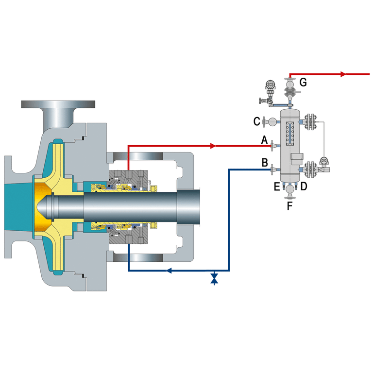
La caractéristique déterminante d'un joint tandem (Agencement 2) est son utilisation d'un système de fluide tampon non pressurisé ou à basse pression. Le fluide tampon dans la cavité inter-joints est maintenu à une pression inférieure à la pression du procédé à étancher, souvent proche de la pression atmosphérique ou légèrement supérieure pour faciliter la circulation et garantir que la cavité reste remplie. L'API 682 stipule explicitement qu“” un fluide tampon est un fluide entre les joints interne et externe, qui est à une pression inférieure à la pression de la chambre d'étanchéité ».
En fonctionnement normal, le joint primaire supporte la pleine différence de pression du fluide de procédé. Le joint secondaire subit une différence de pression minimale, typiquement inférieure à 5 PSI. Cette configuration permet au joint secondaire de rester en mode veille, subissant une usure minimale jusqu'à ce que le joint primaire commence à défaillir.
Le fluide tampon circule par convection naturelle ou avec l'aide d'une bague de pompage. La chaleur générée par le joint primaire entraîne le schéma de circulation, le fluide plus froid entrant par le bas et le fluide plus chaud sortant par le haut.
Joints Mécaniques Doubles (Agencement API 3)
Définition Détaillée et Architecture de Conception
Les joints mécaniques doubles, conformes typiquement à l'Agencement API 3, consistent en deux ensembles de faces d'étanchéité disposés dans une chambre d'étanchéité ou une cartouche, avec un fluide barrière dédié circulant dans la cavité entre eux.
La caractéristique déterminante d'un joint double est que ce fluide barrière est maintenu à une pression toujours supérieure à la pression du fluide de procédé à étancher. Cette différence de pression positive est typiquement dans la plage de 1 à 2 bar (15 à 30 psig) au-dessus de la pression du procédé, ou comme spécifié par des normes comme l'API 682 ou les recommandations spécifiques du fabricant (par exemple, minimum 2 bar ou 10% au-dessus de la pression de la pompe).
Principe de Fonctionnement : Le Système de Fluide Barrière Pressurisé
Le système de fluide barrière pressurisé distingue les joints doubles des configurations tandem. La pression du fluide barrière est typiquement maintenue à 20 PSI au-dessus de la pression de la chambre d'étanchéité par diverses méthodes : accumulateurs à vessie d'azote, accumulateurs à piston ou systèmes de pression directe.
Les deux joints dans un agencement double partagent la charge de pression, réduisant la contrainte sur les faces individuelles des joints. Le joint interne empêche le fluide de procédé de pénétrer dans le fluide barrière, tandis que le joint externe contient le fluide barrière. Le fluide de procédé lui-même est ainsi efficacement confiné dans la pompe ou l'équipement.
Types de Joints Mécaniques Doubles
- Agencement Dos-à-Dos: Dans cette configuration, les anneaux rotatifs d'étanchéité sont typiquement montés entre les anneaux statiques d'appui, amenant les joints à être effectivement face à des directions opposées, l'un de l'autre. Il s'agit d'un agencement courant pour les joints doubles à usage général et est spécifié sous l'Agencement API 682 3. Le fluide barrière est typiquement introduit sur le diamètre extérieur (OD) des deux paires de joints.
- Agencement Face-à-Face: Ici, les anneaux statiques d'appui sont montés entre les anneaux rotatifs d'étanchéité, amenant les joints à être face à face. Cette configuration est également utilisée pour l'Agencement API 682 3, le fluide barrière étant souvent sur l'OD des deux joints.
- Agencement Face-à-Dos (Orientation Tandem avec Barrière Pressurisée): Cela implique qu'un anneau d'appui est monté entre les deux anneaux d'étanchéité et qu'un anneau d'étanchéité est monté entre les deux anneaux d'appui, essentiellement une disposition physique tandem mais fonctionnant avec un fluide barrière pressurisé. Cette configuration peut également être utilisée comme joint d'Agencement API 3, le fluide barrière étant typiquement sur le diamètre intérieur (ID) du joint interne et l'OD du joint externe.


