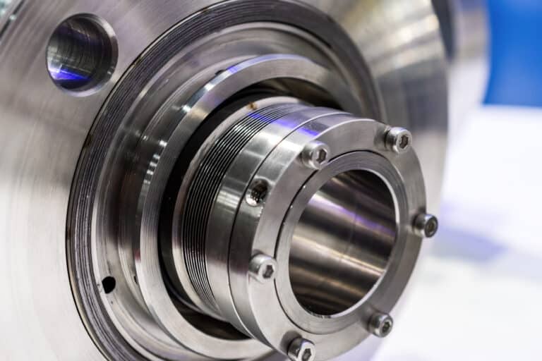
If you only need the definition of what a tandem seal is and how it works (API 682 Arrangement 2 mechanics, buffer fluid basics, when it applies), start with What Is a Tandem Mechanical Seal. This page focuses on the decision between tandem and double — comparison, selection criteria, and cost tradeoffs.
I see engineers argue about “tandem vs double” seals at least once a month — and nine times out of ten, the confusion traces back to terminology, not engineering. The old names describe the same hardware from different angles. Once you translate them into API 682’s Arrangement 2 and Arrangement 3, the selection stops being a vocabulary quiz and becomes a clear decision about containment philosophy: do you need passive backup, or active barrier?
That distinction drives everything downstream — your flush plan, your monitoring burden, your regulatory posture, and your total cost of ownership.
Why “Tandem vs Double” Is the Wrong Question
The industry spent decades calling an unpressurized dual seal a “tandem seal” and a pressurized dual seal a “double seal.” Some manufacturers still do. One major seal manufacturer defines “tandem,” “double,” and “dual” as three separate categories — with overlapping definitions that contradict each other on the same FAQ page.
API 682 resolved this by replacing legacy names with arrangement numbers:
- Arrangement 2 (formerly “tandem”): Two seals per cartridge, outer containment seal chamber at lower pressure than the seal chamber. Uses unpressurized buffer fluid or a dry-running containment seal.
- Arrangement 3 (formerly “double”): Two seals per cartridge with externally supplied barrier fluid pressurized above seal chamber pressure.
The critical insight from Gordon Buck, a member of the original API 682 taskforce: the same physical seal hardware can serve as either Arrangement 2 or Arrangement 3. The difference is entirely in the support system and pressurization philosophy. When the 2nd Edition expanded Arrangement 3 to permit face-to-back, face-to-face, or back-to-back configurations, it confirmed that the arrangement number reflects a containment strategy — not a mechanical design.
In the mid-1990s, multiple facilities experienced Arrangement 2 seal failures and process fluid releases because operators didn’t understand the containment philosophy behind their seals. After the industry adopted proper buffer fluid monitoring and alarm protocols, seal arrangement best practices pushed mean time between failures past 100 months on some installations. The terminology wasn’t academic — getting it wrong had operational consequences.
How Arrangement 2 and Arrangement 3 Actually Work
Arrangement 2 is a passive backup system. The primary (inboard) seal contacts process fluid directly and handles the full pressure differential. The outer (containment) seal sits in an unpressurized buffer fluid environment or runs dry. Under normal operation, the containment seal does almost nothing — it exists to catch leakage if the primary seal fails.
Buffer fluid in an Arrangement 2 system will become contaminated over time. That is a feature, not a flaw. Normal leakage past the primary seal migrates into the buffer cavity, making the buffer fluid itself the monitoring medium. A rising buffer fluid level or changing composition signals primary seal degradation long before catastrophic failure.
Arrangement 3 works on a fundamentally different principle. Barrier fluid is pressurized above seal chamber pressure, creating a positive pressure differential that prevents process fluid from ever reaching the outer seal. Both seal faces run in clean barrier fluid. Process fluid never contacts the outer seal under normal conditions — contamination of barrier fluid indicates a seal failure event, not routine operation.
The API 682 qualification testing for Arrangement 2 containment seals reveals this philosophical difference in concrete terms. These seals undergo a two-phase test: 100 hours on propane at 10 PSI, then 100 hours on diesel at 40 PSI, followed by a static hold at 250 PSI for four hours. The test simulates inner seal failure because the containment seal is designed to eventually face process fluid. Arrangement 3 outer seals never see process fluid under normal conditions — a completely different design assumption.
Flush Plan Pairing and Cost
The arrangement determines your flush plan, and the flush plan determines your real operating cost. This is where most engineers underestimate the Arrangement 2 vs 3 decision.
Arrangement 2: Plan 52
Plan 52 pairs with Arrangement 2. It circulates buffer fluid through an external reservoir with a pumping ring inside the seal — no external pressure source. The system is simple: a reservoir, tubing, and a level or pressure alarm. Maintenance is minimal, and the components are inexpensive relative to pressurized alternatives.
Arrangement 3: Plan 53A or 53B
Arrangement 3 requires pressurized barrier fluid, which means Plan 53A, 53B, 53C or 54 — the two compared here are 53A and 53B. The choice between them hinges on one number: seal chamber pressure.
Plan 53A uses an external pressurized gas source (typically nitrogen) to maintain barrier fluid pressure a minimum of 20 to 25 psig above maximum process pressure. It works well, but it has a hard ceiling at 150 psig. Above that pressure, gas absorption into the barrier fluid degrades seal face lubrication and creates unpredictable pressure behavior.
Once seal chamber pressure exceeds 150 psig, Plan 53B with a bladder accumulator (or Plan 53C or 54) becomes necessary. The bladder physically separates pressurizing gas from barrier fluid, preventing absorption. Plan 53B handles pressures up to 750 psig — but it adds a heat exchanger, bladder maintenance, and higher monitoring frequency. The tradeoff: wear particles in Plan 53B systems recirculate through the seal chamber because they have no place to settle, potentially accelerating face wear.
The cost gap between these flush plan options is not trivial. Plan 52 needs a reservoir and tubing. Plan 53A adds a nitrogen supply, circulation device, cooling coil, and replenishment system. Plan 53B adds all of that plus a bladder accumulator and heat exchanger. Specifying Arrangement 3 when Arrangement 2 would serve the application doesn’t just add upfront cost — it adds decades of barrier fluid management, nitrogen supply logistics, and monitoring complexity.
The 4-Question Selection Test: Arrangement 2 or 3?
Rather than defaulting to Arrangement 3 for safety or Arrangement 2 for cost, run through these four questions in order. Each one either narrows or decides the choice.
Question 1: Can Your Process Fluid Reach the Atmosphere at All?
If the answer is absolutely not — the fluid is acutely toxic, carcinogenic, or regulated under zero-emission mandates — Arrangement 3 is the only option. Active pressurized barrier is the only arrangement that prevents process fluid migration by design. Arrangement 2 allows primary seal leakage into the buffer cavity as normal operation.
Question 2: Does EPA Method 21 Apply?
If your facility operates under an LDAR program with EPA Method 21 screening at 1,000 ppm, you need to evaluate whether Arrangement 2’s containment performance meets that threshold consistently. For many volatile organic compounds, Arrangement 3 with clean barrier fluid provides a wider compliance margin. The API 682 standard specifically references this 1,000 ppm screening value.
Question 3: What Is Your Seal Chamber Pressure?
If you’ve determined Arrangement 3 is required, this question selects the flush plan. Below 150 psig, Plan 53A works and costs less. Above 150 psig, Plan 53B, 53C or 54 is mandatory regardless of budget preference. This threshold is not negotiable — gas absorption at higher pressures compromises barrier fluid integrity.
Question 4: Can You Tolerate Managed Leakage Past the Primary Seal?
This is the philosophical question at the heart of the decision. Arrangement 2 assumes the primary seal will leak small amounts of process fluid into the buffer cavity over time. If the process fluid is non-polymerizing, non-toxic in small quantities, and your monitoring system can detect buffer fluid contamination reliably, Arrangement 2 with Plan 52 delivers equivalent safety at lower lifecycle cost.
A petrochemical facility learned this lesson the hard way. An Arrangement 2 containment seal on a butadiene pump ran for four years at 44 degrees C and 8.2 bar seal chamber pressure — with no seal support system installed. Butadiene leaked past the primary seal, polymerized in the containment cavity, filled the gas lift grooves, and eventually caused a fire. The arrangement choice was wrong for a polymerizing fluid, and the execution made it worse: no support plan, no leakage collection, only a pressure gauge for monitoring. The containment seal that was supposed to be a safety backup became a time bomb because the containment philosophy was never implemented.
The Selection Comes Down to Containment Philosophy
The tandem-vs-double debate disappears once you ask the right question: does this application need a passive safety net or an active pressurized wall? Arrangement 2 with proper Plan 52 implementation handles the majority of dual-seal applications at lower complexity and cost. Arrangement 3 is non-negotiable when zero process emission is the requirement — and when it is, the 150 psig threshold decides whether you run Plan 53A or invest in 53B, 53C or 54.
One thing I’d add that most specification sheets won’t tell you: the single most common dual seal failure I investigate is an arrangement with no support system. Specify based on containment philosophy, match the arrangement to a flush plan from day one, and verify the support system is actually installed and monitored before startup.