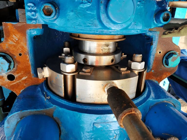
I’ve pulled failed seals from pumps where the seal itself was fine, the material selection was correct, and the installation was textbook. The flush arrangement was wrong for the application. That single specification error caused more downtime than every other choice combined.
The HVAC world treats internal flush as universally superior and external flush as something to avoid. That advice works for clean water — and gets people into serious trouble everywhere else. The real question is never “which is better” but “what does my process fluid demand?”
How Internal and External Flush Arrangements Work
Internal and external flush differ in one fundamental way: where the flush fluid comes from.
Internal Flush (Plans 11, 13, 21)
Internal flush recirculates the pumped product itself back to the seal chamber. API Plan 11 — the most common arrangement — routes a small stream from pump discharge through an orifice to the seal chamber, then back to suction. The seal chamber must stay at least 3.5 bar (about 50 psi) above the fluid’s vapor pressure, or 1.3 times it where that is not achievable, to prevent vaporization at the seal faces.
Plan 13 reverses the flow direction, using seal chamber pressure to push fluid through an orifice back to pump suction. Plan 21 adds a cooler to the Plan 11 circuit when the process runs too hot for the seal faces.
The advantage is simplicity. No external piping, no separate fluid supply, no product contamination risk. The pumped fluid lubricates and cools the seal faces directly.
External Flush (Plans 32, 54)
External flush introduces a clean fluid from an outside source — completely independent of the pumped product. Plan 32 injects clean liquid at 10-25 psi above seal chamber pressure, creating a positive pressure barrier that keeps process fluid away from the seal faces.
Plan 54 takes this further with a pressurized barrier fluid system for dual seals, used when zero process leakage to atmosphere is required.
External flush requires additional infrastructure: piping, pressure regulation, a clean fluid supply, and ongoing monitoring. But it gives you something internal flush cannot — complete isolation of the seal from the process fluid.
When Internal Flush Is the Right Choice
Internal flush works when the pumped product does double duty as a seal face lubricant. Clean water, light hydrocarbons, and non-polymerizing chemicals at moderate temperatures all qualify.
The critical check is temperature rise across the seal faces. Each fluid type has a different tolerance: water and low-vapor-pressure hydrocarbons allow roughly 15 deg F rise, lubricating oils tolerate about 30 deg F, and high-vapor-pressure products allow only 5 deg F before flashing begins. These numbers determine whether a simple Plan 11 recirculation provides enough cooling or whether you need Plan 21 with a heat exchanger.
For clean-service applications — HVAC circulating pumps, boiler feed water, clean condensate — internal flush is the correct choice. It eliminates external piping complexity, removes the risk of flush fluid contaminating the process, and costs less to install and maintain. The API 682 standard specifies this for a reason: when conditions permit, simpler is better.
Where engineers get into trouble is assuming “clean enough” when the process fluid is marginal. If solids content exceeds 1-2% by weight, or if the fluid polymerizes at seal face temperatures, internal flush will destroy the seal faces within weeks.
When External Flush Becomes Mandatory
External flush is not a fallback option — it is the engineering-required solution for any process where the pumped fluid cannot safely lubricate the seal.
I’ve seen this failure pattern dozens of times in heavy industrial applications: a pump running solids-laden fluid with nothing but a Plan 11 recirculation loop. The abrasive particles in the process stream grind across the seal faces, score the carbon, and embed in the softer face material. Within months, leakage paths develop that no amount of spring force can close. In severe cases, debris blocks the seal faces from closing entirely, and the seal locks in an open position.
The solution is straightforward — Plan 32 or Plan 54, depending on whether single or dual containment is needed. By injecting clean external fluid at higher pressure than the seal chamber, you keep every particle in the process stream away from the seal faces.
External flush is mandatory in these conditions:
- Abrasive or solids-laden fluids (slurries, mineral processing, wastewater with grit)
- Fluids that crystallize or polymerize at seal face temperatures
- Hazardous or toxic media requiring zero emissions (Plan 54 with barrier fluid)
- High-temperature services where the process fluid degrades at seal face conditions
- Fluids with poor lubricity that would cause dry running at the faces
External flush is the only viable option for hundreds of process applications across refining, chemical, pharmaceutical, and mining industries. Calling it “inferior” disregards this engineering reality.
How to Select the Right Flush Arrangement
The selection starts with one question: is the pumped product a good seal face lubricant?
If the answer is yes — the fluid is clean, within temperature limits, non-polymerizing, and provides adequate film between the faces — internal flush is your default. Start with Plan 11 and only add complexity (Plan 13, 21, 23) if thermal or pressure conditions require it.
If the answer is no — the fluid is abrasive, hazardous, crystallizing, or thermally unstable at seal conditions — external flush is mandatory, not optional. The flush plan selection then becomes a question of containment level: Plan 32 for single seals needing clean isolation, or Plan 54 for dual seals requiring zero-emission containment.
A practical decision sequence:
- Step 1: Characterize the process fluid. Solids content, vapor pressure at seal temperature, lubricity, chemical stability, toxicity classification.
- Step 2: Apply the lubricant test. Will this fluid protect two lapped faces running at shaft speed without scoring, vaporizing, or depositing solids?
- Step 3: If yes → internal flush. Select the specific plan (11, 13, 21, 23) based on seal chamber pressure margin and the temperature rise tolerance for your fluid type.
- Step 4: If no → external flush. Select Plan 32 (clean external injection) or Plan 54 (pressurized barrier system) based on emissions requirements.
- Step 5: Verify that flush flow rate and pressure meet the seal manufacturer’s specifications. For Plan 32, the baseline is 1 gpm per inch of seal size at 3,600 rpm, with pressure 10-25 psi above seal chamber pressure.
What the spec sheet doesn’t tell you is that the decision hierarchy runs counterintuitively. The most restrictive option is no flush at all — it demands perfect fluid conditions. Bypass (internal) flush is the practical default for clean services. External flush adds cost and complexity but solves problems that internal flush physically cannot.
Common Specification Errors and Their Consequences
The most expensive specification error I encounter is applying HVAC logic to process applications. Engineers who learned on clean-water systems default to internal flush everywhere, and the seals pay the price.
A Caribbean refinery learned this the hard way with Plan 32 on light-cycle oil pumps. The external flush arrangement was technically correct — the slurry service required it — but nobody evaluated the economic impact. Hundreds of barrels per day of refined gas oil used as flush liquid crossed into the coker charge and was lost. The seal survived; the operating budget didn’t. Flush arrangement selection isn’t just a reliability question — it’s an economic one.
The reverse error is equally dangerous. Specifying internal flush for a dirty or hazardous service because “it’s simpler” leads directly to accelerated seal face wear, increased emissions, and unplanned shutdowns.
A third failure mode has nothing to do with the arrangement choice itself. Even a correctly specified external flush system fails when the support infrastructure breaks down — barrier fluid lines blocked by contamination, operators starting pumps without circulators running, or 25-year-old support equipment that no longer meets current API 682 requirements. Before replacing a proven seal design, check the support system first.
The Bottom Line
Flush arrangement selection is an engineering decision driven by process fluid properties, not a preference between “good” and “bad” options. Apply internal flush where the process fluid serves as a capable seal face lubricant. Specify external flush where it doesn’t — and budget for the infrastructure to support it properly.
Start every specification with the fluid analysis, not the seal catalog. That sequence — fluid first, then flush plan, then seal arrangement — prevents more premature failures than any material upgrade or design improvement. The API 682 standard codifies this approach because decades of field failures proved the alternative doesn’t work.