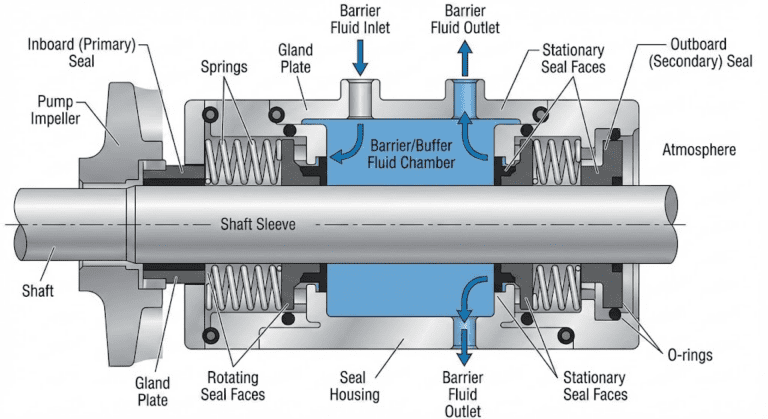
A mechanical seal is a shaft seal built from two flat, lapped rings pressed face to face — one turning with the pump shaft, one held stationary in the housing — closing the leak path where the shaft passes out of the pressurised casing. An oil seal does a related job with a rubber lip riding directly on the shaft surface; a mechanical seal seals on two end faces held together by springs and by the pressure in the seal chamber.
It does not stop leakage. The faces need a fluid film between them to survive, and that film is the leak path. A working mechanical seal controls leakage down to parts per million of vapour, a rate that takes instrumentation to detect at all, which is why a seal can be doing its job perfectly while the shaft under it looks dry.
The reason to fit one in place of gland packing is that control of leakage — packing is adjusted to weep for its own lubrication, and a mechanical seal is not.
How a Mechanical Seal Works
A mechanical seal works by holding two flat faces together hard enough to seal and lightly enough to keep a lubricating film between them. Springs supply the closing force when the pump is stopped or the chamber pressure is low. Once the pump is running, most of the closing force comes from hydraulic pressure in the seal chamber acting on the back of the primary ring.
The faces run in contact through that film and both of them wear — slowly while the film holds, and very fast once it does not.
The Three Sealing Points
A mechanical seal has three sealing points: between the two faces, between the rotating unit and the shaft or sleeve, and between the gland plate and the seal chamber.
Only the first is supposed to leak. The other two seal on static or slow-moving surfaces, need no lubricating film, and are designed to pass nothing at all. A seal wetting the shaft under the gland has a failed O-ring or gasket, and lapping the faces will not touch it.
The Fluid Film Between the Faces
The film between the faces is commonly 5 to 50 microinches thick, and nobody machines it — its thickness is set by the combined surface roughness of the two rings.
Leakage across the faces is proportional to the pressure and to the cube of that film thickness, so a gap that doubles leaks eight times as much. Flatness is therefore specified in helium light bands: two bands is 23 microinches, and shop specifications usually call for two or three. Thermal and pressure distortion in service can open a face to ten bands or more, which no amount of bench lapping prevents.
In absolute terms, normal is modest. A volumetric leakage rate of 3 ml/hr is about 60 drops an hour, roughly a drop a minute.
Dry Running
Dry running — the faces turning with no liquid between them — is among the most frequent causes of mechanical seal failure, and among the fastest. With no film the faces contact directly, the friction heat has nowhere to go, and the sliding surfaces are destroyed; the elastomers immediately behind them usually overheat at the same time.
Carbon against silicon carbide tolerates brief episodes better than any other common pairing, and it is the core standard for seals specified to run dry. No face material survives it indefinitely.
Parts of a Mechanical Seal
A mechanical seal has five groups of parts, and most of them go by two or three different names depending on whose catalogue is open in front of you.
- Primary sealing elements: the two faces. The primary ring is also called the face, the rotating face or the seal ring; the mating ring is also called the seat, the stationary face or the stator.
- Secondary sealing elements: the O-ring, wedge or bellows sealing the primary ring to the shaft or sleeve, plus the static gaskets closing every other path. The dynamic one either slides along the shaft or deforms in place.
- Drive elements: set screws, pins, dents, tabs, keys and squeezed elastomers, transmitting torque to the rotating parts and holding the stationary parts against rotation.
- Load elements: the springs. A circular arrangement of small coils, one large single coil, or a metal bellows doing the spring and the sealing job together.
- Adaptive hardware: gland plates and shaft sleeves. When they make the seal a self-contained unit it is a cartridge seal; when they do not, it is a component seal.
How Seal Face Materials Are Paired
The default is one hard face against one soft face, because the softer ring conforms to the harder one as both distort under pressure and temperature. Silicon carbide against carbon graphite is the most common pairing and tungsten carbide against carbon the second.
That pairing gives a low coefficient of friction, a low combined surface roughness and the ability to run in, and it tolerates the limited face contact that occurs in every seal. Between the two hard candidates, silicon carbide conducts heat away from the faces roughly 50 % better than tungsten carbide, which keeps the film more stable.
Two hard faces are the answer to abrasive slurry, where particles embed in a soft carbon face and then grind the mating ring. The trade-off is that hard materials are not self-lubricating, so when a hard/hard pair loses its film the damage begins immediately. The modern version of that pairing is a silicon carbide grade with graphite inclusions, which puts small lubricating reservoirs in the hard face without creating leak paths.
What the wrong pairing looks like when the seal comes back to the shop:
- Two silicon carbide faces, scored and heat-marked: the film was too thin for a pair that cannot lubricate itself. Either the duty needs more film or it needs a soft face back.
- Bulges ringed by cracks on the carbon face: blistering. It occurs almost exclusively in carbon graphite, most often on viscous oils, and it calls for a blister-resistant grade.
- Rings cracked on start-up after a shutdown: the two flat faces adhered while the pump stood, and the starting torque broke a ring or its drive.
- A tungsten carbide ring corroded across the face: acidic media attack the cobalt binder.
Types of Mechanical Seals
A mechanical seal is described by four independent choices: one pair of faces or two, balanced or unbalanced, pusher or bellows, component or cartridge. Every seal on the market has a position on all four, and those four together are the selection decision — the catalogue type names are shorthand for particular combinations.
Single or Dual
A single seal has one pair of faces; a dual seal has two, with a fluid between them. If that fluid sits below process pressure it is a buffer and the arrangement is unpressurised; above process pressure it is a barrier and the arrangement is pressurised. API 682 calls the three cases Arrangement 1, 2 and 3, and dual seals are built face-to-back, back-to-back or face-to-face.
There are two reasons to pay for the second pair of faces. Emissions is the first: as a general guide, a general-purpose single seal brings emissions down to around 1,000 ppm, while a pressurised dual seal with a liquid barrier fluid brings them to zero.
Lubrication is the second. The inboard faces then run on the barrier fluid, which matters when the process fluid is a poor lubricant — low specific gravity, low vapour pressure, high viscosity, or abrasive particles in suspension.
Balanced or Unbalanced
Balance is how much of the seal-chamber pressure is allowed to act on closing the faces. An unbalanced seal lets the full chamber pressure push the primary ring against the seat, so the closing load climbs with pressure and the seal runs out of film at fairly modest pressures. A balanced seal steps the sleeve or the face so only part of that area is hydraulically loaded, holding the closing load down as pressure rises.
Pusher or Bellows
A pusher seal keeps the primary ring in contact with the seat through a secondary seal that slides along the shaft or sleeve as the face wears; a bellows flexes in place instead. A sliding secondary seal can hang up on a fretted sleeve, on deposits, or on its own swelling, and once it does the face stops following the seat. A bellows has no sliding surface to hang up on.
Metal bellows go further and remove the elastomer altogether, which widens the temperature range in both directions; with flexible graphite as the static secondary seals they cover duties outside any elastomer’s range. O-ring pusher seals hold higher pressure in return, since bellows convolutions have to stay thin to keep the spring rate low. API labels the pusher Type A and the metal bellows Type B.
Component or Cartridge
A component seal is a set of loose parts the fitter sets to a measured height on the shaft. A cartridge seal arrives as one pre-assembled unit — sleeve, gland and seal together — that bolts on before its setting clips are pulled.
The cartridge is factory-set for face loading and alignment and can be air-tested before it ships, so there is far less for the fitter to get wrong. It costs more and needs a seal chamber with space for it.
The field evidence is less emphatic than the sales argument. Across single-seal installations, association survey data showed no large leakage improvement for cartridge designs over component designs. The case for cartridge is strongest where the people fitting seals are not seal specialists.
What API 682 Means for the Seal You Buy
API 682 governs seals for centrifugal and rotary pumps in petroleum, natural gas and chemical service, and where it applies it makes most of the choices above before the buyer gets to them.
Every API 682 seal is a cartridge. The default face pair is silicon carbide against premium blister-resistant carbon graphite. Designs must pass a qualification test set out in a normative annex for the services they are sold into, and the assembled cartridge is air-tested before shipping.
The scope is bounded. It covers shaft diameters from 20 mm (0.75 in.) to 110 mm (4.3 in.), with pressure and temperature limits set by seal category. A seal running outside those conditions is designated an Engineered Seal, and the standard’s requirements no longer cover it.
If the pump is an ANSI, HVAC, water or general chemical duty, the seal in it is not an API seal. Those seals are dimensioned by EN 12756 and ISO 3069, and nothing behind them corresponds to API’s qualification testing, so you are relying on the supplier’s own test evidence.
How Long a Mechanical Seal Lasts
There is no lifespan figure for a mechanical seal, only a reliability record for a population of them. In recent industry reliability data, 60 months mean time between failures is the benchmark most sites want to be at, midstream operations often treat 48 months as acceptable, and some majors target 100 months.
The three-year number that circulates comes from API 682’s objective of 25,000 hours. It was written as a target, enough readers treated it as a guarantee that the sentence was deleted from the standard, and the figure itself is being removed in the current update.
Where a given site lands is set by the duty and by how the pump is operated far more than by which seal was bought.
Why Mechanical Seals Fail
Mechanical seals mostly fail because of what is happening around them. In a two-year dataset of 3,500 pump failures across 18 end users, the root causes of premature seal failures split into operations 49 %, maintenance 28 % and engineering 23 %.
The seal is also the component most often recorded as having failed — about 60 % of all pump failures in that dataset. Some of that is the seal genuinely failing and some of it is bookkeeping. The operator sees a visible leak and writes “seal failed” on the repair notification, whatever started the sequence.
Operations covers the familiar list: dry running, valves closed, priming, cavitation, process upsets, cooling and flushing systems that stopped flowing. Maintenance covers alignment, assembly, seal setting, clearances, bearings and shaft runout. Engineering covers duty specification, pump and seal selection, seal housing dimensions and shaft stiffness.
For a repair, the practical consequence is to read the failed faces before ordering the replacement. A seal fitted back into an unchanged duty fails the same way.