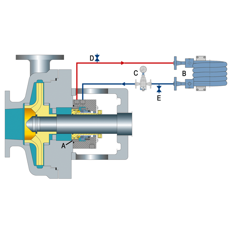
You pull a failed seal out of a centrifugal pump, and there it is: a coil spring behind an O-ring, both riding on the shaft sleeve. That is a pusher mechanical seal — the most common seal type in general-purpose pumping. Most seals a maintenance technician handles daily are pusher designs, and understanding how that O-ring moves along the shaft is the single most useful thing you can learn about how these seals work and why they fail.
How a Pusher Seal Works
A pusher mechanical seal maintains face contact through a simple mechanism: a spring pushes a dynamic O-ring along the shaft, which in turn keeps the primary seal faces pressed together.
Here is what happens step by step. The spring applies an axial load to the seal’s rotating assembly. That load transfers through the O-ring, which slides along the shaft or sleeve surface toward the stationary face. As the carbon face wears — even fractions of a millimeter — the spring advances the O-ring further to compensate. The seal faces stay in contact without any manual adjustment.
The dynamic O-ring is what makes a pusher seal a pusher seal. It moves axially to accommodate wear, vibration, and thermal growth of the shaft. This sliding motion also provides damping during shaft vibration, which helps stabilize the seal under transient conditions. But that same friction between the O-ring and shaft is also what causes the most common failure mode: fretting — microscopic surface damage from the constant cyclic movement.
The shaft surface underneath the O-ring must be smooth enough for the ring to slide freely. A surface finish of 15 RMS or finer is standard. Anything rougher, and the O-ring hangs up — it stops sliding, the spring can no longer compensate for face wear, and the seal leaks.
Key Components
Every pusher seal shares four basic elements: a spring (or springs), a dynamic secondary seal (the O-ring), a rotating seal face, and a stationary seal face. The spring and O-ring are what distinguish this design from non-pusher types like bellows seals.
Spring Types
Single-spring designs use one heavy-coil spring wrapped around the shaft. The thick wire resists corrosion well and handles dirty fluids, but the load distribution across the seal face is not perfectly uniform. These are the go-to choice for slurry or particulate-laden applications where smaller wire would clog.
Multi-spring designs distribute the load through several smaller springs arranged around the seal’s circumference. Load distribution is more even, and they resist centrifugal unwinding at high shaft speeds better than a single coil. The tradeoff: thinner wire corrodes faster in aggressive chemistries.
Wave springs occupy less axial space — useful when seal chamber depth is tight. Force variation with deflection is higher, so precise setting height matters more during installation.
Balanced vs Unbalanced
This distinction controls the pressure range. Unbalanced pusher seals handle up to about 200 psig. Balanced designs extend that to 3,000 psig by reducing the hydraulic closing force on the seal faces, which also lowers heat generation and power consumption.
Before you start selecting a seal, know your sealed pressure. If it exceeds 200 psig, you need a balanced design — no exceptions.
Common Applications and Limitations
Pusher seals work well in water, light hydrocarbons, mild chemicals, and most general-service pump applications. They are affordable, widely available in standard sizes, and compatible with a broad range of elastomer materials for the O-ring.
The limitations come from that same sliding O-ring. In abrasive slurry service, solids build up between the O-ring and shaft, causing hang-up. The O-ring stops moving, the faces lose contact, and the seal fails. High-temperature applications above roughly 400 degrees F degrade standard elastomer O-rings, pushing you toward PTFE wedge rings or, more often, toward a non-pusher bellows seal that eliminates the dynamic secondary seal entirely.
Cryogenic service is another boundary. Standard elastomers lose flexibility at extremely low temperatures, and the O-ring cannot slide reliably on a cold shaft.
If your application involves abrasive particles, extreme temperatures, or cryogenic conditions, a pusher seal is the wrong choice. For most general-service pump applications, it is the right one.
How to Spot a Pusher Seal on Your Pump
When you disassemble a pump or inspect a seal in the field, look for three things: visible springs (single coil or multiple small springs), an elastomer O-ring sitting on the shaft or sleeve, and a carbon or hard-face ring pressed against a stationary seat.
If you see springs and an O-ring riding on the shaft, it is a pusher seal. If you see a thin corrugated metal tube (a bellows) instead of springs and an O-ring, it is a non-pusher design.
The most common mistake I see is technicians reinstalling a pusher seal without checking the shaft surface under the O-ring. Run your fingernail across it. If you feel a groove or ridge — that is fretting damage. The new O-ring will hang up in that same spot within weeks. Either replace the sleeve or polish the shaft to 15 RMS before installing the new seal. If you skip this step, you will be back in a week doing the same job.
The One Thing to Remember
Every pusher seal depends on one moving part doing its job: the O-ring sliding along the shaft. That single mechanism is what compensates for wear, absorbs vibration, and keeps the faces sealed. It is also what fails first when conditions turn against it — rough shafts, abrasive fluids, or excessive heat.
When you evaluate whether a pusher seal fits your application, ask one question: can the O-ring slide freely for the entire expected service life? If yes, a pusher seal will serve you well for years. If anything in the process will impede that movement, look at a bellows design instead.