A refinery hot-oil pump arrived in the shop after six months. The faces were clean, but the bearing housing was full of water and the bearing was blue — Plan 62 had done its job and destroyed the pump at the same time. The data sheet read “steam available from header,” and the rest was left to the utility group. Plan 62 works for hot hydrocarbon service when four numbers on the data sheet are right.
How Plan 62 Sweeps the Atmospheric Side
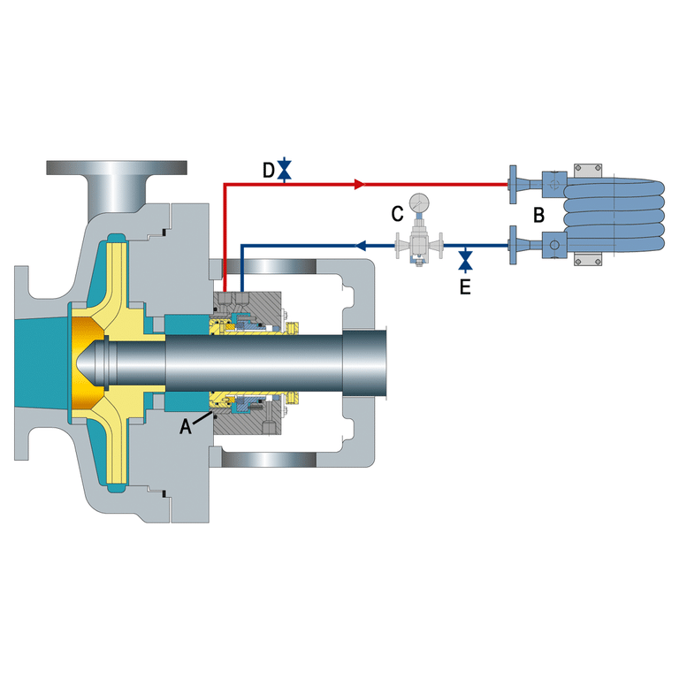
Plan 62 circulates a low-pressure fluid — almost always steam — through the gland chamber on the atmospheric side of a single seal. The sweep clears the outboard face of leakage before it can oxidize, coke, crystallize, or ice, and the quench fluid never touches process.
A steam tap delivers fluid, a close-clearance throttle bushing restricts where it exits, and a gland drain routes most of the steam to a condensate header. The bushing decides whether Plan 62 keeps working between overhauls. Plan 62 is not pressurized containment — for barrier or buffer sealing against atmosphere, you want Plan 52 or 53A under API 682.
What Pressure Plan 62 Actually Runs At
Plan 62 operates at 2 to 5 psig (0.14-0.34 bar) at the gland — low enough to sweep, never high enough to seal. EagleBurgmann publishes 0.2-0.3 barg, Flexaseal 2-7 psi, FSA training 2-4 psi with 5 psi as the upper limit.
The number that confuses specifiers is AESSEAL’s “maximum 1 bar (14.5 psig)” figure: that is the mechanical rating of the gland connection, not an operating setpoint. Writing 14.5 psig forces condensate past the throttle bushing within hours of startup.
The binding constraint is not pressure. Steam temperature must not exceed process temperature. Saturated steam at 50 psig is 298°F; on a 250°F hydrocarbon that header flashes the inboard faces. Regulate the supply to 2-5 psig (~218-227°F saturated) and treat the regulator as part of the seal scope.
When Steam Is the Right Quench Fluid (And When It Isn’t)
Quench fluid choice is gated by process temperature, not by which utility is nearest. Vendor pages list steam, nitrogen, and water as parallel options. They are not.
| Fluid | Service envelope | Failure outside |
|---|---|---|
| Steam | Hot hydrocarbon, 121-300+°C | Needs trap + drain |
| Nitrogen | Cryogenic / sub-zero | No cooling for hot service |
| Clean water | < ~93°C, chloride < 50 ppm | Flashes; chlorides drive SCC |
| Process condensate | Steam unavailable | Carries contamination |
I’ve seen clean water specified on a 280°F hydrocarbon because the steam header was on the wrong side. The water flashed at the gland, atmospheric-side cooling collapsed, and the seal coked through in six weeks.
The Coking Window That Defines the Service Envelope
Plan 62 belongs to a specific window — hot enough that hydrocarbons coke on the atmospheric carbon face, not so hot that the inboard faces flash. Nick Poulitsis at Technoseal puts carbon-face coking onset at 121°C (250°F); Turbomachinery Magazine puts the “specify by default” boundary at 177°C (350°F) or any known coking service.
Between those numbers, Plan 62 is a judgment call; above 177°C, it stops being optional. Steam quench is preventative — once coke has formed, the quench cannot remove it.
How Plan 62 Fails on the Atmospheric Side
When a Plan 62 service returns to the shop, check the bearing housing and gland plate before pulling the seal — the quench side fails differently than the process side.
- Wet-steam face flashing. Droplets hit the hot atmospheric face, flash, and lift the face — practitioners call it an “explosion.” Fix: thermodynamic trap, branch line, lowest point, near the seal.
- Condensate flooding the bearing housing. Worn bushings let steam blow past toward the bearing; condensate displaces lube oil and the bearing runs dry. Turbomachinery Magazine documented one refinery case that ended in ignition — red-hot bearing, primary-seal leak, fire.
- Drain restrictions. Drain piping must be free-draining — no traps, loops, or orifices.
- Throttle-bushing wear. Service life is shorter than the seal’s. Inspection means measuring bushing clearance, not just face condition.
When Plan 52 or 53A Replaces Plan 62
Plan 62 supports a single seal. Above the temperature where the inboard faces can no longer stay below vapor pressure, atmospheric-side quench cannot help. A dual seal replaces the architecture, not supplements it. API 682 4th Edition assigns Arrangement 2 (Plan 52 unpressurized buffer) and Arrangement 3 (Plan 53A pressurized barrier) for hydrocarbons above ~177°C with flashing risk, zero-emission requirements, or chronic coking. The decision logic across hot-service flushing options picks which arrangement fits.

Where Most Plan 62 Specifications Go Wrong
Before the data sheet leaves engineering, write four numbers into it. Quench operating setpoint 2-5 psig (not the gland connection rating). Saturated steam temperature below process temperature. Trap type and location: thermodynamic, branch line, lowest point, near the gland. Drain piping: free-draining.
The most common Plan 62 misdiagnosis I see is a hot-service seal returned for “premature face failure” when the root cause is on the atmospheric side. Before replacing the seal, check the bearing housing for water and the gland for stress cracking. The seal is usually fine — Plan 62 inherited whatever steam the utility group sized for general process use.