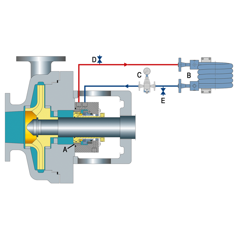
Both “throat bush” and “throttle bush” appear in parts lists and technical documentation, but they occupy different positions in the seal assembly. Confusion arises because they perform similar functions, creating restrictive clearances around the shaft. The difference comes down to location: throat bush sits inboard near the impeller, throttle bush sits outboard in the gland plate.

What Is the Difference Between Throat Bush and Throttle Bush?
Position is the definitive differentiator between these two components.
Position-Based Distinction
The throat bush mounts between the impeller and the seal chamber in a pump. It faces the process fluid and controls flow into the seal environment.
The throttle bush mounts at the atmospheric end of the gland plate in mechanical seals. It faces atmosphere and restricts leakage from the seal to the outside.
When examining a seal assembly drawing, identify the impeller side (inboard) versus the atmospheric side (outboard). The throat bush is always inboard; the throttle bush is always outboard.
Quick Reference Comparison Table
| Feature | Throat Bush | Throttle Bush |
|---|---|---|
| Location | Inboard (impeller side) | Outboard (gland plate) |
| Installation | Pressed into casing cover | Pressed into seal gland |
| Primary function | Controls flow from pump to seal chamber | Restricts leakage from seal to atmosphere |
| Clearance to shaft | 0.015-0.020 inch (0.40-0.51 mm) | Varies by type: 0.007-0.040 inch |
| API reference | API 610/682 | API 682 |
Throat Bush: Function, Location, and Specifications
The throat bush controls fluid flow from the pump chamber into the seal environment. Its clearance directly affects seal chamber pressure and temperature, making it critical for flush plan performance.
Location and Installation
The throat bush presses into the casing cover with a 0.002-0.003 inch (0.05-0.08 mm) interference fit. This tight fit to the casing ensures the component stays in position under process pressure differentials.
The clearance to the shaft or sleeve measures 0.015-0.020 inch (0.40-0.51 mm). This gap is engineered to create controlled flow rather than act as a seal.
Primary Functions
For API Plan 11 applications, the throat bushing creates optimal pressure in the seal chamber by restricting return flow to the pump suction. Without proper throat bushing clearance, seal chamber pressure drops below design values.
For API Plan 23 systems, the throat bushing separates the cool seal chamber from the hot process. A properly functioning throat bush maintains a temperature drop of 11-28C (20-50F) between process and seal chamber. When this temperature differential narrows, suspect throat bushing wear.
As noted in industry practice: “The only purpose for a throat bushing is to control the fluid in the seal chamber either to increase pressure (for example a plan 11) or to limit interchange with the pumped fluid (for example a plan 23).”
Clearance Specifications
- Throat bushing to shaft: 0.015-0.020 inch (0.40-0.51 mm) clearance
- Throat bushing to case: 0.002-0.003 inch (0.05-0.08 mm) interference
Verify these specifications against your pump OEM documentation. Clearances outside tolerance indicate replacement is needed.
Materials
Standard throat bush materials include:
- Stainless steel (general service)
- Bronze (non-sparking applications)
- Carbon (floating types)
- PEEK composites (high-performance, carbon fiber-reinforced)
- Engineered plastics
Select materials based on fluid compatibility and temperature requirements. For material selection guidance, consider both the process fluid and flush media properties.
Throttle Bush: Function, Location, and Specifications
The throttle bush provides secondary containment at the atmospheric end of the seal. It restricts leakage from the seal chamber to atmosphere and enables failure detection in API Plan 66A/B systems.
Location and Installation
The throttle bush presses into the seal gland plate, forming a close clearance around the sleeve. Its position at the atmospheric end means it must tolerate potential dry-running contact with the shaft.
I recommend selecting throttle bush materials that accept occasional shaft contact without galling. Carbon and bronze remain the preferred choices for this reason.
Primary Functions
The throttle bush serves as a containment device. In normal operation, it restricts minor seal weepage from reaching atmosphere. In the event of primary seal failure, it limits leakage and provides time for controlled shutdown.
For hydrocarbon applications, secondary containment bushings can restrict leakage at full pipeline pressure. John Crane’s secondary containment bushing, for example, handles up to 1500 psi (103 bar) in failure scenarios.
Clearance Specifications by Bushing Type
| Bushing Type | Diametral Clearance | Application |
|---|---|---|
| Fixed throttle | 0.025-0.040 inch | API Category 1 (default) |
| Floating carbon | 0.007-0.011 inch | API Category 2/3 (default per 4th edition) |
| Segmented | 0.001-0.002 inch effective | Category 2/3 option (tightest) |
Historically, throttle bushings had a nominal 0.025 inch diametral clearance. Modern API 682 editions require tighter clearances for higher reliability categories.
Materials
Throttle bush materials must be non-sparking and accept dry-running contact:
- Carbon (primary choice: non-sparking, no static buildup)
- Bronze (non-sparking applications)
Avoid materials prone to galling with the shaft or sleeve material.
When a Throttle Bush Is Specified (and When It Is Not)
Not every mechanical seal installation includes a throttle bush. The bush is standard equipment in:
- Double / dual mechanical seal arrangements — almost always required for secondary containment
- API Plan 62 quench and Plan 66A/B failure-detection systems — the throttle bush creates the back-pressure or leak-detection cavity those plans depend on
- Hazardous-fluid applications — anywhere leakage to atmosphere must be controlled, restricted, or routed to a drain
- Systems requiring leak direction — when seal weepage must be guided to a specific collection point rather than allowed to drip freely
You typically will not see a throttle bush in:
- Basic single-seal setups with no flush or containment requirement
- Non-critical services where minor external leakage is acceptable (water transfer, non-hazardous duty)
- Older pump designs that predate modern API 682 containment requirements
Check your seal assembly drawing or parts list. For API 682 specifications, Category 1 defaults to a fixed throttle bushing; Categories 2 and 3 default to a floating bushing that can move slightly with the shaft. If the drawing shows no bushing at all and the service has containment implications, the original pump design predates current API guidance and the seal is likely under-specified.
API 682 Bushing Requirements by Category
API 682 4th edition changed the default bushing requirements. Practitioners trained on earlier editions should update their specifications.
Category Defaults (4th Edition)
| API Category | Default Bushing Type | Notes |
|---|---|---|
| Category 1 | Fixed throttle bushing | Standard for low-duty applications |
| Category 2 | Floating bushing | Changed from fixed in earlier editions |
| Category 3 | Floating bushing | Highest reliability requirement |
Fixed vs Floating Bushings
Fixed bushings mount tight in the housing with no radial clearance on the OD. They offer simpler design but cannot accommodate shaft deflection or runout.
Floating bushings have clearance on the OD, allowing radial motion. When shaft deflection occurs, the bushing follows rather than forcing contact. This design reduces galling risk and accommodates dynamic shaft movement.
When to Specify Each Type
For stable shaft operation with minimal deflection, fixed bushings suffice. Specify fixed bushings for Category 1 applications and lower-pressure services.
For pumps with expected shaft deflection, always specify floating bushings. Category 2 and 3 applications require floating bushings by default. The tighter clearances of segmented carbon bushings work best when you need maximum containment with acceptable light rubbing.
Can Throat Bush and Throttle Bush Be Used Interchangeably?
No. These components are designed for different positions and functions. Interchanging them creates operational problems.
Position-Specific Design Considerations
The throat bush is sized to create optimal flow and pressure in the seal chamber for specific API plans. Its clearance works with the pump’s hydraulic characteristics to establish target seal chamber conditions.
The throttle bush is sized for containment and leakage restriction. It must tolerate atmospheric-side conditions including potential dry running. Using a throat bush in the throttle position risks improper containment. Using a throttle bush in the throat position disrupts seal chamber pressure control.
Terminology in Industry Practice
Some contexts use these terms loosely:
- Low-pressure stuffing boxes: “throat bushing” terminology more common
- High-pressure applications: “throttle bushing” terminology preferred
- Slurry pumps: “throat bush” names a different part entirely. It is a suction-inlet wear component that forms the pump chamber with the plate liner, not the bushing at the seal chamber neck. If the drawing puts it at the suction, it is not a seal part.
Always verify position in the parts diagram before ordering. Cross-reference OEM documentation to confirm correct part numbers for your specific application.
How to Identify Correct Part for Your Pump
Follow this systematic approach to ensure correct part specification.
Step 1: Locate Component in Assembly Drawing
Examine the cross-section drawing. Identify the impeller position and the atmospheric end of the gland.
- Component inboard of seal faces = Throat bush
- Component outboard in gland plate = Throttle bush
Step 2: Reference API Plan
The mechanical seal flushing plan determines throat bushing criticality:
- Plans 11, 13, 14, 21, 23, 32: Throat bushing critical for pressure/temperature control
- Plans 66A, 66B: Throttle bushing in gland for containment and failure detection
Step 3: Check OEM Part Numbers
Cross-reference manufacturer documentation. Verify clearance specifications match your API category requirements. Part numbers alone may not distinguish throat from throttle bushings clearly, especially when third-party suppliers use different naming conventions.
Step 4: Specify Materials Based on Application
- Standard process: Stainless steel or carbon
- Non-sparking required: Bronze or carbon
- Abrasive or slurry service: PEEK composite or stainless, sized to hold clearance as the bushing wears
For high-temperature applications, consider selecting mechanical seals for high temperature environments when specifying compatible bushing materials.
Conclusion
Correct bushing identification starts with position: throat bush is inboard, throttle bush is outboard. Always check throat bushing clearance when replacing seals to prevent repeat failures.
For assistance specifying throat or throttle bushings for your seal application, contact our engineering team.