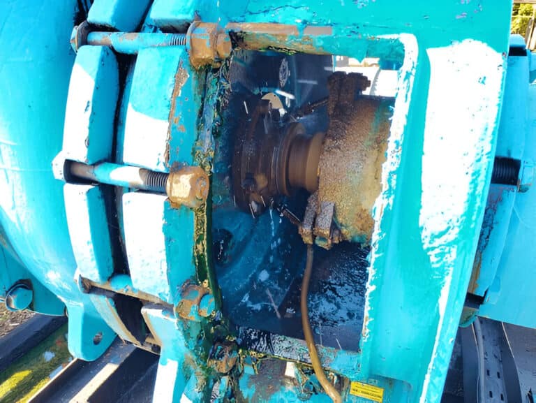
Search for “floating bushing” and most results describe duo-cone face seals used on excavator final drives — an entirely different component. A floating bushing in a mechanical seal system is a cylindrical clearance device mounted with radial freedom inside the seal gland or housing, designed to restrict leakage while following shaft movement. The distinction matters: one is a face seal for heavy equipment, the other is a precision flow restrictor inside a pump seal chamber.
I see engineers confused about this regularly, and the confusion costs time during specification reviews. A floating bushing has a close clearance to the shaft on its inner diameter and a deliberate clearance on its outer diameter, allowing it to shift radially when the shaft deflects or whips. This radial freedom is what makes a floating bushing different from the fixed throttle bushings and throat bushings that serve similar flow-restriction roles but cannot accommodate shaft movement.
What Is a Floating Bushing
A floating bushing is a cylindrical device with a close clearance to the shaft or sleeve that restricts flow between two regions. What makes it “floating” is the clearance on its outer diameter relative to the housing, which allows radial motion should the bushing contact the rotating shaft. The original Durametallic patent specified a shaft-to-bushing radial clearance of just 0.002 to 0.004 inch, with circumferentially spaced springs urging the bushing against a fixed annular face in the gland.
Three bushing positions exist in a seal assembly, and any of them can be floating:
- Throat bushing — the inboard bushing between the seal chamber and the impeller, restricting process fluid flow into the seal environment.
- Throttle bushing — the outboard bushing at the atmospheric end of the gland plate, serving as a containment device.
- Thermal bushing — installed in dual seal arrangements between the inboard and outboard seals, managing barrier or buffer fluid circulation.
“Floating” describes the mounting method, not the position. A throat bushing can be floating. A throttle bushing can be floating. The API 682 standard specifies which positions require the floating design based on seal category and arrangement.
How the Self-Centering Mechanism Works
Spring-loaded contact between the bushing face and a fixed annular face in the gland holds the bushing while letting it follow the shaft radially. When the shaft deflects — from bearing wear, thermal growth, or hydraulic loads — the bushing tracks that movement rather than forcing the shaft against a rigid bore.
Fixed bushings behave like labyrinth seals: because the bushing is rigidly attached to the housing, clearances must be set large enough to prevent destructive contact under worst-case shaft deflection. The result is a clearance of 0.015 to 0.020 inch between bushing and shaft. A floating bushing, following shaft gyrations, holds a much tighter annular gap because the risk of sustained rubbing drops sharply.
The spring mechanism is simple but critical. If springs lose tension — from corrosion, fatigue, or improper installation — the bushing loses its ability to track shaft movement. I’ve pulled floating bushings from glands where the springs were corroded to the point that the bushing was effectively fixed in place, running at designed clearances that assumed radial freedom. The seal still worked, but leakage was higher than it should have been, and the maintenance team never knew why.
Carbon is the default material for both the bushing and the mating gland insert. Carbon provides three properties that matter: dimensional stability under temperature cycling, self-lubricating behavior during incidental contact, and sufficient hardness to resist erosion from process fluid particles.
Fixed vs Floating Bushing Performance
A floating throat bushing reduces the clearance by more than half compared to a fixed bushing. Fixed bushings typically run 10 to 15 mils (0.254 to 0.381 mm) diametral clearance. Floating bushings cut that to less than half while maintaining reliable, non-contact operation.

The leakage impact is direct. Large-clearance fixed bushings have the highest leakage rates. Floating bushings with reduced clearance leak far less. Floating segmented bushings — where the bushing is split into multiple rings — achieve the lowest leakage rates of all three configurations.
What about contact risk? In a database of approximately 19,000 mechanical seal repairs, throttle bushing contact occurred in only 1.6% of cases. Mating ring contact showed up in just 0.3%. Among true API 682 seals, only five mating ring rub incidents were found — two from bearing failures and three from installation misalignment. The data shows that tighter clearances do not meaningfully increase contact frequency when the bushing is free to float.
The fixed-vs-floating decision is the most important bushing specification choice in a seal system, yet most engineers spend more time selecting face materials than getting this right.
When to Specify a Floating Bushing
Fixed throttle bushings default to Category 1 applications only under API 682 4th Edition — the simplest, lowest-risk service. Categories 2 and 3, which cover the majority of refinery and petrochemical pump applications, default to floating bushings.
The API 682 seal coding system uses “L” to designate a floating bushing. When you see that letter in a seal specification code, the engineer has consciously specified radial freedom over a fixed installation.
Minimum clearance specifications from API 682 4th Edition:
- Shafts up to 60 mm: 1 mm (0.039 inch) diametral clearance minimum
- Shafts over 60 mm: 2 mm (0.079 inch) diametral clearance minimum
Before the 4th Edition, API 682 did not specify a minimum clearance between the sleeve and mating ring at all. The addition of these minimums reflects industry recognition that clearance management — not just seal face design — directly controls leakage and reliability.
For applications outside the API framework, the decision follows the same logic: if shaft deflection, thermal growth, or process variability exists in any meaningful degree, specify a floating bushing. Fixed bushings remain appropriate only when shaft conditions are truly stable and leakage tolerance is high.
What the Spec Sheet Misses About Real Operating Conditions
Spec sheets give you clearance values at ambient temperature with a perfectly concentric shaft. That is not what your bushing sees in service.
Thermal growth changes clearances during operation. A common rule of thumb for thermal bushing clearance is 0.002 inches per inch of shaft diameter — but this assumes steady-state temperatures. During startup, the shaft heats faster than the housing, temporarily tightening clearances beyond design intent. During shutdown, the reverse happens: the shaft cools and contracts, opening clearances and allowing higher leakage until temperatures equalize.
I’ve seen floating bushings that performed perfectly at steady state but showed elevated leakage during every startup cycle. The maintenance team was chasing seal face issues when the real problem was transient clearance behavior at the bushing. Once they accounted for thermal transients in the clearance calculation, the startup leakage disappeared.
Material selection compounds this. PTFE bushings are tempting for chemical compatibility, but PTFE changes dimensions noticeably with temperature. Carbon does not change dimensions much with temperature changes — that dimensional stability is why carbon has been the default bushing material since the original patent specified it. PTFE should only enter the conversation when the process fluid is chemically incompatible with carbon, and even then, the dimensional instability needs to be designed into the clearance allowance.
Carbon-fiber-reinforced PEEK is emerging as a next-generation option. It enables tighter clearances without the contact-damage risk of metallic or pure carbon designs, addressing the central tension in all bushing engineering: how tight can you run the gap before contact becomes destructive? The combination of a floating mount and a contact-tolerant material may eventually shift clearance philosophy entirely.
The Bottom Line
The floating bushing is not an exotic component — it is the default containment device for any mechanical seal application above API 682 Category 1. Its value is simple: tighter clearances, lower leakage, and tolerance for the shaft movement that every pump generates in real service.
The specification decision is equally simple. If your application falls into API 682 Category 2 or 3, the floating bushing is already the standard. For Category 1 or non-API applications, evaluate shaft deflection and leakage requirements — and err toward floating when in doubt. The marginal cost increase over a fixed bushing is trivial compared to the leakage reduction and operational flexibility you gain. Start with carbon material, size the clearance for thermal transients, and verify spring condition during every seal change-out.