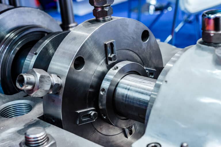
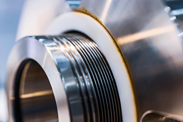
You open a seal chamber during a routine pump overhaul and notice the throat bushing bore is visibly scored. The flush line was delivering flow, the seal faces looked fine at last inspection, yet here you are pulling a failed seal six months early. That worn bushing changed everything downstream — flush flow, seal chamber pressure, face temperature — and nobody flagged it.
A throat bushing is a close-clearance restriction ring installed at the entrance of the seal chamber, between the impeller side of the pump and the mechanical seal. Its job is hydraulic: it controls how much process fluid enters the seal chamber and at what pressure. Every API 682 flush plan that relies on controlled seal chamber conditions depends on this component doing its job.
What a Throat Bushing Does
Fluid flow through the annular gap of a throat bush (also written throat bushing) in a centrifugal pump is proportional to the cube of the clearance. Double the clearance on a worn throat bushing, and flow through that gap increases eightfold. That single relationship explains why a component with a seemingly generous 0.025 inch diametral clearance can make or break your seal environment.
The throat bushing restricts process fluid flow from the pump volute into the seal chamber. On flush plans like Plan 11, this restriction creates the pressure differential that drives flush circulation across the seal faces. On Plan 32, it isolates the seal chamber from process-side pressure, keeping clean external flush fluid where it belongs.
One misconception I encounter regularly: engineers specifying tight throat bushing clearances to “catch the shaft” during bearing failure events. API 682 states explicitly that seal components are not to be considered shaft catchers to restrict shaft movement. The bushing’s purpose is hydraulic — flow restriction and pressure maintenance — not mechanical protection. Specifying clearances based on shaft-catching logic leads to galling, premature bushing wear, and exactly the kind of seal environment instability the bushing was supposed to prevent.
The throat bushing also functions as a thermal barrier. By restricting the volume of hot process fluid entering the seal chamber, it helps the mechanical seal assembly maintain a lower operating temperature at the faces. When that restriction degrades, face temperature climbs, and elastomers start to suffer.
Clearance Specifications
API 682 fourth edition finally codified what end users had been applying informally for decades. The minimum diametral clearances are straightforward:
| Shaft Diameter | Minimum Diametral Clearance |
|---|---|
| Up to 60 mm | 1 mm (0.039 inch) |
| Over 60 mm | 2 mm (0.079 inch) |
For standard throat bushings, a 0.015 to 0.020 inch diametral clearance is the practical baseline most pump repair guidelines start from. The API values above are minimums for the mating ring and other stationary seal parts, not for the throat bushing.
The real question is how much clearance increase you can tolerate before seal performance degrades. A database of approximately 19,000 seal repairs found that only 1.6% of seals showed any throttle bushing contact, and just 0.3% had mating ring contact. Of five mating ring rub incidents on API 682 seals, two traced to bearing failures and three to severe misalignment during installation. The bushings themselves were not the problem — the rotating equipment was.
Throat bushing clearances are generally adequate when the pump runs within its design envelope. The failure mode to watch for is not contact from too-tight clearance. It is excessive clearance from wear that destroys the hydraulic restriction the seal needs.
For a 2 to 3 inch shaft, typical new clearance starts at around 0.014 inch diametral. Industry practice suggests renewal at approximately 0.020 inch — a seemingly small change, but remember the cubic relationship. That 43% increase in clearance roughly triples the flow through the gap.
Fixed vs Floating Bushings
The API 682 fourth edition revised the default gland-plate (throttle) bushing type by seal category. Fixed throttle bushings are now the default for Category 1 only. Categories 2 and 3 default to floating bushings.
The logic is practical. A floating bushing self-centers around the shaft sleeve, accommodating shaft deflection without metal-to-metal contact. This allows tighter clearances — and therefore better flow control and higher maintained seal chamber pressure — without the galling risk that a fixed bushing would face under the same conditions.
For Category 1 services — chemical-duty pumps at moderate temperature and pressure — a fixed bushing with standard clearances handles the job. The shaft typically runs true enough that contact is not a concern.
Categories 2 and 3 cover heavy-duty API 610 pumps with a wider operating window: higher temperatures and pressures. Shaft deflection is more likely under these operating loads.
A floating bushing absorbs that movement while still maintaining hydraulic restriction. If you are specifying a throat bushing for a non-API pump, use the same category logic as your guide — match bushing type to service severity, not to habit.
Material Selection by Process Condition
Composite materials get pitched as universally superior for throat bushings. That is an oversimplification.
Carbon fiber-reinforced PEEK and similar polymer composites eliminate the galling risk between bushing and shaft sleeve. They allow tighter clearances, which means better flow control.
For clean water, light hydrocarbons, and moderate-temperature chemical services below 260 C, composites are the right call. API 610’s ninth edition recognized nonmetallic wear rings for a reason — the galling advantage is real.
But process conditions drive the decision, not material preference. In abrasive slurry services, polymer composites erode much faster than hardened metals. A PEEK bushing in a phosphoric acid slurry pump may last months; a Hastelloy bushing in the same service could last years.
For services above 260 C, most composite formulations lose mechanical integrity. High-temperature thermal oil or reactor services may require 316 stainless steel or nickel alloys despite the wider clearances needed to prevent galling.
Start with process temperature and fluid cleanliness. Clean service below 260 C favors composites for the tighter clearance advantage.
Abrasive or high-temperature services favor metals, accepting the wider clearance as a necessary trade-off. Do not let a material sales pitch override the process data in front of you.
How to Evaluate Throat Bushing Condition During Seal Maintenance
Every seal chamber inspection should include a throat bushing assessment, yet I rarely see it on standard maintenance checklists. A worn bushing is the silent contributor to seal failures that get blamed on the seal itself.
Temperature Differential Check
A properly functioning throat bushing maintains a temperature drop of 11 to 28 C between the process side and the seal chamber. Measure both temperatures during normal operation — process fluid temperature at the pump casing and seal chamber temperature at the gland. When that differential narrows below 11 C, the bushing has likely worn enough to allow excessive process fluid bypass.
This is the easiest field check available. No disassembly required, no special tools beyond a contact thermometer or infrared gun. I make it part of every seal flush system audit.
Visual and Dimensional Inspection
During a seal change, measure the throat bushing bore diameter and compare it against the shaft sleeve outer diameter. Calculate the diametral clearance.
If you are above the renewal threshold for your shaft size — roughly 0.020 inch for a 2 to 3 inch shaft — replace the bushing before installing the new seal. Putting a new seal behind a worn bushing is the most common way to turn a routine seal change into a repeat failure.
Look for scoring, grooving, or uneven wear patterns on the bushing bore. Asymmetric wear indicates shaft deflection or misalignment — problems the new seal will inherit if you do not address them.
Why a Worn Bushing Costs More Than It Looks
The throat bushing is a hydraulic device, not a passive spacer. Its clearance directly controls seal chamber pressure, flush flow distribution, and face temperature — and that relationship is cubic, not linear. A small amount of wear creates disproportionately large changes in seal environment conditions.
Before your next seal installation, measure the throat bushing clearance and check the temperature differential. These two data points take five minutes and can prevent a six-month seal failure from becoming a recurring mystery.