Industry estimates suggest Plan 11 accounts for 50% to 75% of all mechanical seal flush installations. It is the default starting point for single seal applications — and for good reason. A simple flow path from pump discharge, through a control orifice, and into the seal chamber handles the majority of clean-fluid services without external utilities.
Yet most technical references stop at “size your orifice appropriately” without providing the numbers to actually do it. That gap between specification and implementation is where Plan 11 problems start. The difference between a reliable Plan 11 system and one that starves the seal comes down to orifice sizing, piping geometry, and knowing when Plan 11 is the wrong choice entirely.
How API Plan 11 Works
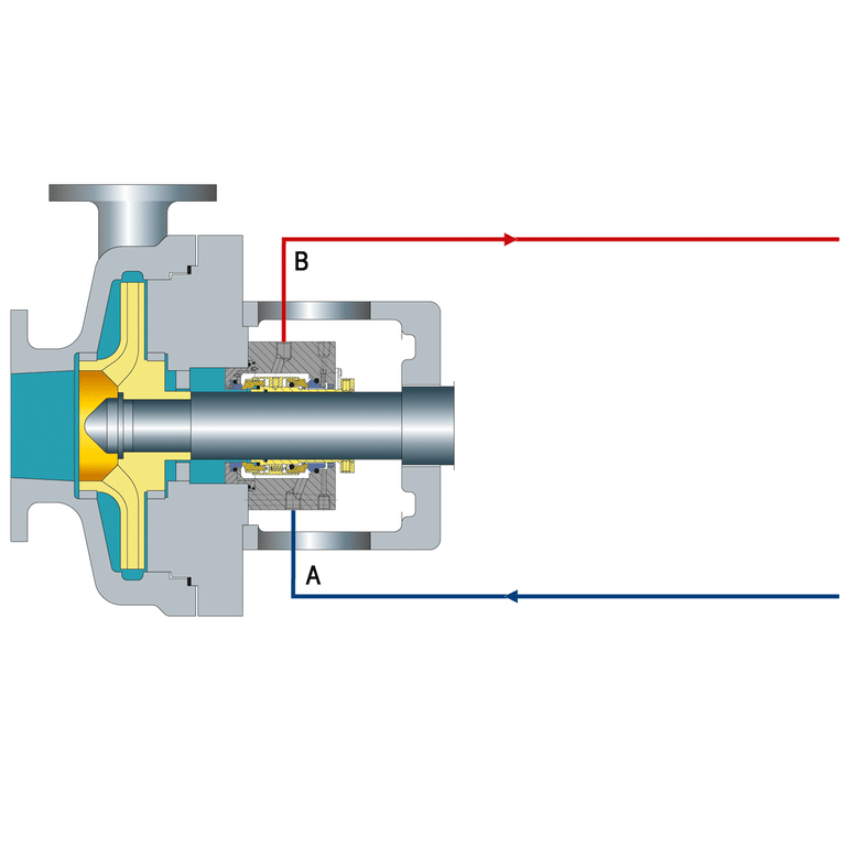
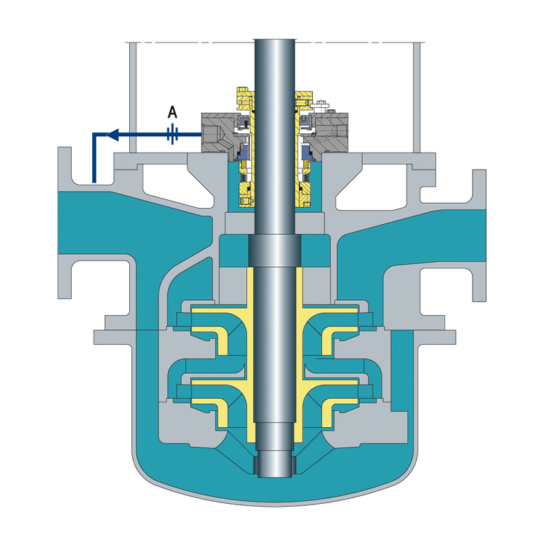
Plan 11 taps process fluid from the pump discharge nozzle (or volute), routes it through a flow control orifice to reduce pressure, and delivers it to the seal chamber at a controlled flow rate. The recirculated fluid cools the seal faces, removes heat generated by friction, and maintains a liquid film across the sealing interface.
The flow path is self-venting on horizontal pumps — vapor moves continuously upward from the seal chamber to the discharge connection, provided the flush line rises continuously from the seal to the discharge. This slope prevents vapor pockets from forming in the flush line. Air locks in Plan 11 piping interrupt cooling flow and destroy seal faces within hours.
Plan 11’s advantage is simplicity — no external reservoir, no cooler, no additional pump. The process fluid itself does the work.
Seal reliability depends less on seal design and more on controlling the environment around the seal faces: pressure, temperature, and fluid cleanliness. Plan 11 achieves that control through discharge recirculation with orifice-throttled flow.
One installation rule that gets violated constantly: never install isolation valves in Plan 11 flush piping. A closed isolation valve cuts flow to the seal entirely, and the seal runs dry before anyone notices the pressure gauge.
How to Size a Plan 11 Orifice
Orifice sizing determines whether your seal gets adequate cooling or runs starved. The minimum practical orifice diameter is 1/8 inch (3 mm) — anything smaller clogs too easily in service. Most Plan 11 installations use orifices between 1/8 inch and 3/16 inch.
At 100 psi differential pressure across the orifice, typical flow rates are:
- 1/8 inch orifice: approximately 2-3 GPM
- 3/16 inch orifice: approximately 5-7 GPM
These values are approximations — actual flow depends on fluid viscosity, orifice geometry, and the exact pressure differential between the discharge tap point and the seal chamber. But they give you a starting point for sizing calculations.
The differential pressure driving the flow equals the difference between pump discharge pressure (at the tap point) and seal chamber pressure. For a standard end-suction centrifugal pump, seal chamber pressure runs close to suction pressure. A pump with 150 psi discharge and 50 psi suction provides roughly 100 psi differential to work with.
When a single 1/8 inch orifice cannot reduce pressure enough without passing more flow than required, use multiple orifices in series. Space them at least 150 mm (6 inches) apart — closer spacing creates interference patterns that distort the pressure drop calculation.
For most applications, target a flush flow rate of 1 GPM per inch of seal size as a baseline. A 2-inch seal needs roughly 2 GPM. Adjust upward for high-temperature services where additional cooling is required.
When Plan 11 Fails — and What to Check First
Plan 11 handles clean, moderate-temperature fluids reliably. Push it outside those boundaries, and failures become predictable.
Orifice Plugging
High-viscosity fluids — crude oil, heavy hydrocarbons, slurries with suspended solids — plug orifices progressively. The seal does not fail immediately. Flow degrades over days or weeks, and by the time the seal overheats, the root cause is invisible without instrumentation.
The practical diagnostic: monitor temperature across the orifice. A temperature drop exceeding 10% from baseline indicates the orifice is restricting. This field rule of thumb catches plugging before the seal fails, and it requires nothing more than two thermocouples and a baseline reading at commissioning.
Venting Problems in Confined Spaces
API 682 requires continuously rising flush lines to prevent vapor accumulation. In tight pump arrangements — SAGD oil sands operations, offshore platforms, retrofit installations — rigid piping cannot always achieve the required slope.
I worked on a project where small SAGD pumps had Plan 11 seals in a space so tight that rigid piping could not maintain a continuously rising path. The vendor recommended adding a vent valve, but that introduced an operator dependency — forget to close the vent valve after startup, and product flows out of the system.
The solution was substituting tubing for rigid piping. Tubing bends where rigid pipe cannot, achieving the required slope within the confined envelope without adding any operator-dependent valve.
Temperature and Coking Limits
Plan 11 recirculates process fluid, so the flush temperature equals process temperature minus whatever cooling the piping provides (minimal). If the process fluid cokes, polymerizes, or flashes at seal face temperatures, Plan 11 accelerates the problem rather than solving it.
Any service where the seal chamber temperature approaches the fluid’s vapor pressure margin needs Plan 23 or Plan 32 instead.
Plan 11 vs Plan 23 — When to Switch
Plan 23 adds a heat exchanger in a closed loop — a pumping ring draws fluid from the seal chamber, passes it through a cooler, then returns it to the seal chamber. Taking cooled fluid from discharge is Plan 21, not Plan 23.
If the discharge-to-seal-chamber pressure differential is sufficient and the process fluid temperature stays well below its vapor pressure at seal conditions, Plan 11 works. When process temperature pushes the fluid close to its boiling point at seal chamber pressure, the seal needs cooled flush — Plan 23.
Many engineers switch away from Plan 11 for the wrong reason. They see a seal failure and blame the flush plan, when the actual issue is insufficient differential pressure. If the pressure differential cannot drive enough flow through the orifice, the answer is not a cooler — it is Plan 13, which reverses circulation direction and uses seal chamber pressure to drive flow back to suction.
Plan 11 fails on pressure differential — switch to Plan 13. Plan 11 fails on temperature — switch to Plan 23. Mixing up these two failure modes leads to installing equipment that does not solve the actual problem.
The Plan 11 Failure That Is Really a Monitoring Gap
Start every Plan 11 evaluation with two numbers: the available pressure differential and the process fluid temperature at seal conditions. Differential pressure determines whether Plan 11 can drive adequate flow. Temperature determines whether uncooled recirculation keeps the seal faces in a safe operating window.
The most common Plan 11 failure I see is not a design problem — it is a monitoring gap. Install thermocouples across the orifice at commissioning and establish a baseline. When that baseline shifts by 10%, the orifice is telling you something before the seal does.