
What is API Plan 23
API Plan 23 is an API 682 flush plan for single mechanical seals that circulates process fluid in a closed loop through an external cooler and back into the seal chamber. The circulation is driven by an integral pumping ring (a slotted wheel or helical scroll machined onto the shaft sleeve) that spins inside the seal chamber and acts as a miniature pump. No external fluid is introduced — the fluid being cooled is the same pump product already sitting in the seal chamber, isolated from the main process flow.
This is the distinction that sets API Plan 23 apart from Plan 21. Plan 21 takes fluid from the pump discharge, cools it, and injects it into the seal chamber in a single pass, which means the cooler has to remove heat from the full flush flow continuously. API Plan 23, by contrast, only has to remove the seal-generated heat plus the heat soaked through the pump casing — a significantly smaller thermal load. The result is significantly lower cooling utility consumption and a smaller cooler for the same seal duty. Plan 23 is typically chosen for hot services (commonly above roughly 150°F / 65°C, such as hot water and high-temperature hydrocarbons) where Plan 21 would waste energy cooling the process stream itself.
How Does API Plan 23 Work
In an API Plan 23 system, the pumping ring inside the seal chamber pushes process fluid out through an outlet port, across an in-line heat exchanger, and back through an inlet port into the chamber. In pump P&IDs, this configuration is often labeled API 23 or simply Plan 23. The loop is closed — the fluid that leaves the chamber is the same fluid that returns, just cooler.
As the cooled fluid re-enters the seal chamber, it washes across the mechanical seal faces. It absorbs frictional heat generated at the faces, keeps them at a safe operating temperature, and carries that heat out to the exchanger. Because the circulation is continuous and the volume is small, the seal chamber reaches a stable thermal equilibrium quickly and stays there.
Circulation depends entirely on the pumping ring. That means the system cannot tolerate vapor lock: if air or vapor is trapped anywhere in the loop, the pumping ring — which is designed for liquid, not gas — cannot push flow through the cooler.
API 682 addresses this by requiring the cooler to be mounted close to the seal (typically within 3 m / 10 ft of total tubing and 18–24 in / 45–60 cm above the seal) and by requiring horizontal tubing runs to slope upward at least 40 mm/m (0.5 in/ft) from the seal to the exchanger. A high-point vent is mandatory before startup so that trapped gas can be purged; Plan 21, which uses discharge pressure, is self-venting and does not need this step.
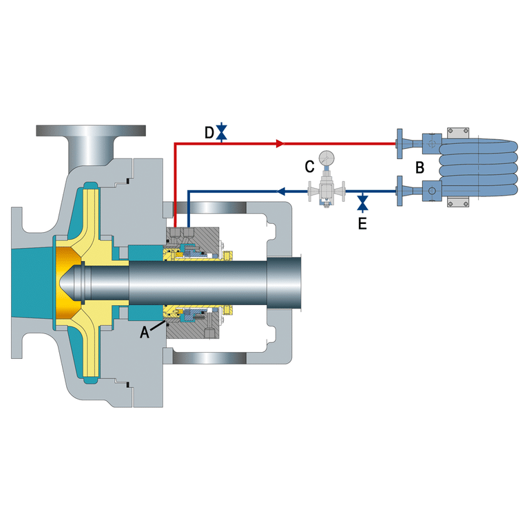
Design of API Plan 23
- Integral circulating device (pumping ring): A slotted wheel or axial-flow scroll machined into the seal sleeve or gland. It rotates with the shaft and generates the pressure rise that drives the loop. No external circulation pump is used.
- External in-line heat exchanger: A shell-and-tube or finned coil cooler sized for the seal-generated plus casing-soak heat load. Per API 682, the exchanger must be oriented so that both the cooling water side and the process side can be completely drained and vented; vertical mounting is generally preferred.
- Inlet and outlet piping with isolation valves: Short tubing runs between the seal chamber and the exchanger, with block valves to allow the cooler to be isolated for maintenance without draining the seal.
- High-point vent valve and drain valve: Required by API 682 to remove vapor from the seal chamber, piping, and exchanger before startup and to drain the loop when the seal is serviced.
- Instrumentation: Temperature indicators at the seal chamber inlet and outlet are standard; a flow switch or sight flow indicator is commonly added to confirm the pumping ring is circulating.
- Optional thermosiphon reservoir: Used only for venting and make-up, never as the primary fluid source. The process fluid stays inside the closed loop.
Advantages of API Plan 23
- Lower utility consumption: Because only the seal-chamber fluid is cooled — not the full flush flow from pump discharge — the cooler is smaller and cooling water demand is much lower than Plan 21 for the same service temperature.
- Preserves process thermal efficiency: Plan 21 removes heat from the process stream itself, which wastes energy the process was designed to carry. Plan 23 isolates the cooling loop from the process, so heat stays in the product where it belongs.
- Cleaner seal environment: Continuous circulation across the seal faces flushes heat and particulates away from the interface, which reduces the risk of thermal cracking on the faces and extends seal life.
- No external fluid compatibility issue: The circulating fluid is the process fluid, so there is no secondary fluid to qualify, source, or monitor for compatibility — a common headache with plans that introduce an external flush.
Disadvantages of API Plan 23
- Installation sensitivity: The pumping ring is a low-head device. Any excess tubing length, undersized cooler, or horizontal low spot that traps gas will choke the circulation. The layout rules (≤3 m tubing, 18–24 in cooler elevation, upward tubing slope, high-point vent) are strict and not optional.
- Not self-venting: Unlike Plan 21, which is driven by pump discharge pressure, Plan 23 must be vented by hand before startup. If the operator skips the vent step, trapped gas can stop circulation and the seal will overheat and fail from lack of face lubrication.
- Initial cost and complexity: The cooler, piping, valves, and instrumentation add installed cost compared to a simple bleed-off plan like Plan 11.
- Limited to liquid service: The pumping ring needs liquid in the chamber at all times. Services that flash, run dry, or have heavy entrained gas are poor candidates; a dual-seal arrangement with a buffer fluid is usually a better fit.
Applications
API Plan 23 is specifically a single-seal flush plan for hot pump services where the process fluid needs to be kept liquid at the seal faces but the cooling cost of a Plan 21 would be excessive. Typical applications include:
- Boiler feed pumps and hot condensate pumps
- Hot oil and thermal fluid circulation pumps
- Refinery hot-service pumps (kerosene, gas oil, residue)
- Hot water services above roughly 150°F / 65°C
- High-temperature chemical process pumps where the process fluid must remain thermally undisturbed