If you already understand what a tandem seal is and need to choose between tandem (Arrangement 2) and double / pressurized dual (Arrangement 3), see Tandem Seal vs Double Seal: How to Choose. This page covers the definition, components, and how a tandem seal works.
API 682 replaced the legacy term “tandem” with “Arrangement 2” because decades of loose terminology had blurred the line between tandem, double, and dual seals. The confusion is real — I still see purchase orders that specify “double seal” when the application clearly calls for an unpressurized tandem configuration. Getting the terminology wrong means getting the piping plan wrong, and that cascades into buffer fluid issues, incorrect pressure settings, and premature failures.
A tandem mechanical seal mounts two seal sets in series, oriented in the same direction, with an unpressurized buffer fluid filling the space between them. The inboard seal handles the process fluid. The outboard seal provides backup containment. Unlike single seal arrangements, this configuration ensures that if the primary seal fails, the secondary seal contains leakage and buys time for an orderly shutdown.
How a Tandem Seal Works
Both seal sets face the same direction — toward the process fluid — with the inboard seal doing the primary sealing work against full process pressure. Buffer fluid circulates in the cavity between the two seals at a pressure LOWER than the process chamber pressure. That below-process pressure relationship is what makes it an API 682 Arrangement 2 seal.
Because the buffer fluid operates below process pressure, it does not create a pressure barrier against the process. It lubricates and cools the outboard seal faces while serving as a leak detection medium. Any process fluid that migrates past the inboard seal contaminates the buffer reservoir, triggering an alarm.
Buffer fluid pressure must remain below seal chamber pressure and below 2.8 bar (40 PSI). Exceed either limit and the arrangement functionally becomes a pressurized dual seal, defeating the purpose and creating compatibility issues.
This architecture gives a tandem mechanical seal a fundamental trade-off: simpler hardware and lower cost than pressurized arrangements, but containment rather than full isolation. For most hydrocarbon and moderately hazardous services, that trade-off is exactly right.
API 682 Arrangement 2 Classification
API 682 formalized the tandem configuration as Arrangement 2 — dual unpressurized. The standard establishes three arrangement categories:
- Arrangement 1: Single seal
- Arrangement 2: Dual unpressurized (tandem) — buffer fluid below process pressure
- Arrangement 3: Dual pressurized (back-to-back) — barrier fluid above process pressure
The Arrangement 2 designation eliminates the ambiguity that plagued the industry for years. When you specify Arrangement 2, every seal manufacturer understands the same configuration: two seals, same orientation, unpressurized buffer fluid, paired with API Plan 52.
API 682 seals carry a reliability target of three years of continuous service. Meeting that target with Arrangement 2 depends entirely on proper buffer fluid management — an area where I see more installations fail than succeed on the first attempt.
API Plan 52 Buffer Fluid System
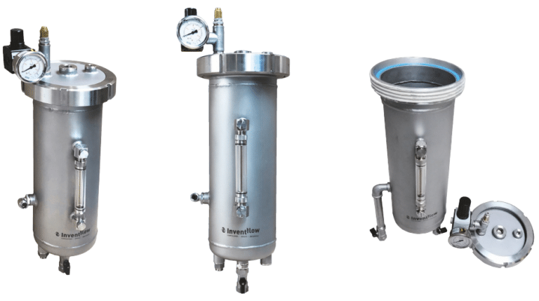
API Plan 52 is the standard piping plan paired with Arrangement 2 tandem seals. The system uses a pumping ring driven by shaft rotation to circulate buffer fluid through an external reservoir in a closed loop. Dual unpressurized configurations are typically noted as Plan 11/52 — Plan 11 for the inboard flush, Plan 52 for the buffer system.
The pumping ring makes Plan 52 self-regulating. Circulation rate depends entirely on the pumping ring’s performance within the closed-loop system — there’s no external flow control valve to adjust. Faster shaft speed means higher circulation and better cooling. At low speeds or during startup, circulation drops, and that’s when face temperatures climb.
The reservoir serves three functions: it holds buffer fluid volume, provides a heat rejection surface, and acts as a leak detection device. A rising liquid level in a non-volatile service signals process fluid migrating past the inboard seal. In volatile services, process leakage vaporizes instead of accumulating — connect the reservoir vent to a vapor recovery system and actual emission rates become very low.
Maintenance Distinction by Service Type
Non-volatile process fluids that leak past the inboard seal accumulate in the reservoir as liquid. Periodic draining and buffer fluid replacement is required — the interval depends on inboard seal condition and process fluid properties.
Volatile process fluids behave differently. Leakage vaporizes on contact with the buffer fluid, so liquid level remains stable even as contamination increases. Monitor buffer fluid quality through sampling rather than level indication alone.
Tandem vs Back-to-Back vs Face-to-Face
The three dual seal arrangements differ in seal orientation, pressure relationship, and failure behavior.
| Parameter | Tandem (Arr. 2) | Back-to-Back (Arr. 3) | Face-to-Face |
|---|---|---|---|
| Seal orientation | Same direction | Opposing, outward | Opposing, inward |
| Fluid type | Buffer (unpressurized) | Barrier (pressurized) | Buffer or barrier |
| Pressure vs process | Lower | 15-30 psi higher | Application-dependent |
| Primary advantage | Backup protection, simplicity | Full process isolation | Compact axial length |
| Pressure capability | Higher (both seals in compression) | Lower (outboard in tension) | Lowest |
| Typical plan | Plan 52 | Plan 53A/53B | Plan 52 or 53A |
Tandem seals have a counter-intuitive advantage in pressure capability. Both seal sets operate as “inside” seals — pressure acts on the outer diameter of the seal faces, keeping them in compression. Back-to-back arrangements put the outboard seal faces in tension because the pressurized barrier fluid pushes from between the seals. Ceramic seal face materials are weaker in tension than compression, which limits the allowable barrier fluid pressure in back-to-back designs.
For most engineers selecting between tandem and back-to-back, the decision comes down to one question: does the application require full containment (back-to-back with pressurized barrier) or is leak detection with backup sealing sufficient (tandem with unpressurized buffer)?
Why Buffer Pressure Direction Defines Tandem Seal Performance
Textbooks describe buffer fluid as a coolant and lubricant for the outboard seal. That description is accurate but incomplete. The pressure direction — buffer below process, barrier above process — defines everything about how the seal system behaves in service.
In a tandem arrangement, the buffer fluid is NOT a containment barrier. Process fluid always has a thermodynamic pathway through the inboard seal into the buffer cavity. The buffer system’s job is to detect that migration and provide time for response, not to prevent it.
I’ve pulled tandem seals from hydrocarbon services where the buffer reservoir had turned dark within weeks of commissioning. The inboard seal wasn’t “failed” in any dramatic sense — it was performing within normal leakage rates. But the buffer fluid told the story. Engineers who don’t monitor buffer fluid condition are running blind on their primary leak detection mechanism.
This leads to a counter-intuitive reality: the buffer fluid in a tandem seal demands MORE maintenance attention than barrier fluid in a pressurized arrangement. Barrier fluid operates at higher pressure than the process, so the pressure gradient actively prevents contamination. Buffer fluid has no such protection. It will contaminate — the only question is how fast.
When Tandem Seals Are Not Enough
Plan 52 tandem seals should not be used in truly toxic applications where any leakage past the primary seal creates an unacceptable hazard. Hydrofluoric acid service in refineries is the classic example. Any HF migration into the buffer reservoir creates a maintenance hazard that an unpressurized system cannot prevent.
For these applications, Arrangement 3 with Plan 53A provides full containment. The barrier fluid pressure — maintained 20 to 25 psi above maximum seal chamber pressure — ensures the pressure gradient always pushes barrier fluid toward the process, not the reverse. The trade-off is chemical compatibility: barrier fluid will leak across the inboard seal faces into the process, so it must be fully compatible with the process fluid.
When an inboard seal fails on a Plan 52 system, the correct response sequence is: alarm triggers on reservoir pressure or level change, operator closes the isolation valve near the reservoir top, and the outboard seal assumes full sealing duty. Plan an orderly shutdown and repair — the outboard seal is a temporary containment device, not a permanent solution.
Selecting the Right Arrangement
Arrangement 2 with Plan 52 covers the majority of dual seal applications in refinery and chemical plant service. It is simpler to install, cheaper to maintain, and more pressure-capable than back-to-back arrangements. But it is not a universal solution.
Specify tandem when the process fluid is hazardous enough to require secondary containment but not so toxic that any buffer fluid contamination is unacceptable. Hydrocarbon services, moderately corrosive chemicals, and volatile organic compounds are the sweet spot. For lethal-service applications, Arrangement 3 with pressurized barrier fluid is the only defensible choice — and the API 682 standard specifies this for a reason.
The most common mistake I see: specifying tandem seals and then neglecting buffer fluid monitoring. An Arrangement 2 installation without a disciplined buffer fluid management program is a leak detection system with nobody watching the detector.