I’ve seen Plan 52 misapplied to truly toxic service dozens of times — usually because someone read a manufacturer page that called it “leakage protection.” It isn’t.
Plan 52, sometimes written as seal plan 52, circulates unpressurized buffer fluid between the inboard and outboard seals of an Arrangement 2 dual cartridge. It’s built for containment and detection, not prevention. What the spec sheet doesn’t tell you is the pressure number, the 28-day working volume rule, or the failure modes that send these systems to the shop.
What Plan 52 Actually Does
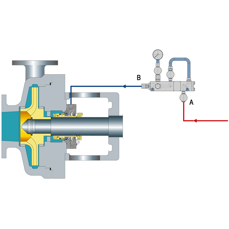
Plan 52 sits between two seals in an Arrangement 2 cartridge (2CW-CW or 2CW-CS) and circulates a non-pressurized buffer fluid through a seal pot that vents to flare or vapor recovery. The buffer does three jobs: cool the inboard seal’s atmospheric side, lubricate the outboard seal, and catch any inboard leakage so the pressure and level instruments raise an alarm before product reaches atmosphere.
The misconception worth correcting up front: Plan 52 does not prevent leakage. Because the buffer system is unpressurized relative to the process, any inboard seal leak flows *from* the process *into* the buffer. That’s by design — the buffer is the expected leak destination, and a rising pot level or a pressure spike is the early warning.
For genuinely toxic or zero-emission service, Plan 52 is the wrong plan — you need a pressurized barrier system where any leak migrates into the process instead. Route Plan 52 to flare-eligible hydrocarbons, VOCs in LDAR-regulated service, and fluids that can safely enter a closed vent header.
What Is the Pressure in API Plan 52?
The buffer fluid is maintained below seal chamber pressure, and API 682 also caps the buffer pressure itself at 0.28 MPa (2.8 bar, 40 psi). In practice, the reservoir headspace sits at 1-3 psig with a continuous vent to the flare or vapor recovery header, so the buffer runs close to atmospheric pressure whatever the chamber pressure.
That ceiling isn’t arbitrary. The inboard seal is designed to hold full chamber pressure against a near-atmospheric buffer, and the outboard seal is only meant to see that low buffer pressure in normal running.
Circulation is another piece competitors get wrong. Gordon Buck and Ralph Gabriel, chief engineers at John Crane, make the point explicitly in *Pumps & Systems*: the internal pumping ring is the primary driver during operation, not the thermosiphon.
The reservoir elevation — typically 18 to 30 inches above the pump centerline — provides about three feet of static head, but that head is a standstill backup, not the running mechanism. If a commissioning team assumes gravity convection will move the buffer, they’ll spec the wrong tubing run and chase low-flow alarms for months.
One counterintuitive point: the low operating pressure does not buy you a low-pressure reservoir. API 682 seal pot commissioning requires the pot and piping to match the pump’s pressure and temperature rating — an inboard seal failure can equalize the reservoir with process pressure in seconds.
The Components That Make Plan 52 Work
A complete Plan 52 system has six elements, and every one of them appears on the P&ID for a reason:
- Seal pot (reservoir) — API 682 4th Edition requires 28 days of working volume without refilling. Typical defaults are 3 gallons for shafts under 2.5 inches and 5 gallons for larger shafts; actual sizing depends on leak rate and thermal load.
- Pumping ring + circulation lines — 3/4 inch (18 mm) tubing is the recommended standard. Smaller chokes circulation; larger wastes working volume in the piping.
- Vent to flare or vapor recovery — Continuous, never valved closed during operation. A blocked vent is the fastest way to lose a Plan 52 system — leaked vapor pressurizes the reservoir and defeats the unpressurized philosophy.
- Instrumentation (PIT, LIT, TIT) — Low-level alarm catches buffer loss; high-pressure alarm catches inboard seal failure; high-temperature alarm catches circulation stall.
- Fill and drain connections — Bottom drain, dedicated fill port. Filling funnels are strongly discouraged because air entrainment stalls the pumping ring.
- Cooling coil (optional) — Required for hot services where buffer temperature would otherwise exceed the fluid’s flash point margin.
Gland porting matters when specifying hardware. For Plan 52 Arrangement 2, the inlet is LBI (liquid buffer inlet) and the outlet is LBO. Swapping them sends buffer backwards through the pumping ring.
Choosing the Right Buffer Fluid
Four criteria drive buffer fluid selection, in this order: vapor pressure, flash point, process compatibility, and toxicity.
Vapor pressure is the constraint most engineers miss. The fluid needs a low vapor pressure, with an atmospheric boiling point at least 28°C (50°F) above the process temperature.
Without that margin, the atmospheric-vented reservoir will flash the buffer, vapor-lock the pumping ring, and starve the outboard seal. That single threshold disqualifies most light hydrocarbons and some alcohols as buffer fluids.
Flash point needs a 25-50°C margin above the buffer’s operating temperature, depending on insurance requirements and local code. Propylene glycol and water-glycol mixes suit hydrocarbon service; diesel or paraffinic oils work for amine or water-reactive service. Water alone is rarely a good Plan 52 buffer — it flashes above 100°C, and any process leak immiscible in water will separate and starve the outer seal.
Practitioners routinely ask how often the buffer should be changed. There’s no universal interval — monitor reservoir level rise and buffer discoloration. A level climbing 1-2 inches per week means the inboard seal is leaking, and that’s a change-out trigger long before any calendar interval.
How Plan 52 Differs from Plan 53A and 53B
The short version: Plan 52 is containment-and-detection at atmospheric-adjacent pressure, Plan 53 is leak prevention at pressurized barrier.
Plan 53A uses a pressurized nitrogen blanket on the reservoir with the barrier fluid at least 1.4 bar (20 psi) above maximum seal chamber pressure. Plan 53B swaps the gas blanket for a bladder accumulator to prevent nitrogen dissolution. Both push barrier fluid *into* the process on any inboard leak — the opposite direction of Plan 52.
The decision boundary is straightforward. If the process cannot reach atmosphere even briefly or cannot be safely routed to flare, spec Plan 53. If the process is flare-compatible and LDAR compliance is the driver, Plan 52 is cheaper and passes the EPA monitoring requirement.
For the full comparison, see the difference between Plan 52 and 53. Engineers who need barrier prevention without nitrogen management should evaluate API Plan 54, which uses an externally pressurized barrier skid.
Plan 52 is paired with a dual unpressurized mechanical seal — typically an Arrangement 2 configuration, which is where Cowseal’s double mechanical seal cartridges are engineered to fit.
Common Failure Modes to Watch For
I’ve pulled Plan 52 systems that failed in four distinct patterns, and each one points to a specific root cause.
Heat checking on the inboard face — Fine radial cracks on the tungsten carbide or silicon carbide face. Root causes: dry startup, inadequate buffer cooling, or scale on the cooling coil throttling heat transfer. Before replacing the seal, check the cooling coil for deposits and verify the pumping ring is actually moving fluid.
Coking on the atmospheric side — Black sludge on the outboard face. Overheated buffer or process contamination breaking down thermally. The Swagelok Edmonton team documents this pattern across Alberta refinery Plan 52 installations — steam clean the debris, and for persistent hot service upgrade to a Plan 62 atmospheric quench on the outboard side.
Blistering on carbon faces — Raised circular sections on the carbon. Porous carbon grade combined with high-viscosity buffer and frequent pump cycling. Spec a denser carbon grade, or switch to silicon carbide if cycling is unavoidable.
Buffer cross-contamination — Reservoir level climbing, buffer darkening, pressure slowly rising. This is expected inboard leakage doing its job, but a fast rise means the inboard seal is near end-of-life.
Buck and Gabriel call out this scenario directly: when the inboard fails completely, the outer seal becomes primary and the PIT alarm is the only early warning that the buffer has lost its unpressurized status. Plan the shutdown on the first sustained pressure rise.
Plan 52 Specification Checklist
Before releasing a Plan 52 datasheet to procurement, confirm the following:
- Buffer pressure target: below seal chamber pressure and below 40 psi (0.28 MPa) per API 682
- Seal pot sized for 28-day working volume (3 gal for shafts < 2.5", 5 gal larger — verify against actual heat load)
- Reservoir and piping rated to pump pressure and temperature, not to buffer operating conditions
- Buffer fluid atmospheric boiling point ≥ 28°C (50°F) above process temperature, flash point margin confirmed
- Vent line continuously open to flare or vapor recovery, no block valve
- PIT, LIT, and TIT installed with low-level, high-pressure, and high-temperature alarm setpoints
- Pumping ring specified and verified during commissioning — not assumed to work because the reservoir sits above the pump
- Process fluid confirmed flare-compatible; truly toxic or zero-emission service routed to Plan 53 instead
The most common Plan 52 failure I see on audit isn’t a seal problem — it’s a specification problem. An engineer picks the right plan, then lets the reservoir get spec’d as a low-pressure tank because “the buffer runs at atmospheric.”
Six months later the inboard seal leaks, the reservoir equalizes with process pressure, and a tank rated for 50 psi is holding back 400. Write the pressure and temperature ratings to match the pump, every time. The buffer pressure is low; the design pressure is not.