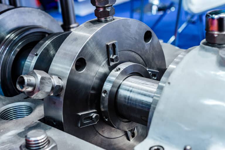
Both buffer fluid and barrier fluid sit between the seal faces of a dual mechanical seal — yet confusing the two can turn a containment system into a liability. The difference is not the fluid itself. It is the pressure relationship between that fluid and the process, and that relationship is dictated by the seal arrangement you selected before the fluid question ever came up.
I see engineering teams spend hours debating water versus oil when the real question — does this application demand zero atmospheric leakage? — has already been answered by their process hazard assessment. The arrangement follows from that answer, and the fluid follows from the arrangement.
The One Difference Between Buffer and Barrier Fluid
The only technical difference is pressure. A barrier fluid is a pressurized fluid (minimum 20 psi above seal chamber) that physically blocks process fluid from crossing the inboard seal face in API 682 Arrangement 3 dual seals.
Buffer fluid operates at a pressure lower than seal chamber pressure. It fills the space between the inboard and outboard seals in an API 682 Arrangement 2 (dual unpressurized) configuration. Because the buffer side runs at lower pressure, process fluid can migrate across the inboard seal into the buffer fluid over time. The outboard seal then acts as a containment seal, preventing that buffer fluid — now potentially contaminated — from reaching atmosphere.
Barrier fluid operates at a pressure higher than seal chamber pressure. In an Arrangement 3 (dual pressurized) configuration, the barrier fluid is actively maintained at a minimum of 20 psi above maximum seal chamber pressure per API 682. This positive pressure differential means process fluid physically cannot cross the inboard seal face. The barrier fluid is the operating environment for both inboard and outboard seals.
| Parameter | Buffer Fluid (Arr. 2) | Barrier Fluid (Arr. 3) |
|---|---|---|
| Pressure vs seal chamber | Lower | Higher (min. 20 psi above) |
| Process fluid migration | Into buffer side (expected) | Prevented by pressure differential |
| Containment guarantee | Leakage detected, not prevented | Zero process-to-atmosphere leakage |
| External pressurization | None required | Required (gas, pump, or accumulator) |
The API 682 standard specifies this pressure relationship for a reason: it makes the classification binary. If the fluid between your dual seals runs below seal chamber pressure, you have buffer service — regardless of what fluid you pour in. If it runs above, you have barrier service. Calling an unpressurized system “barrier” because you filled it with barrier-grade synthetic oil does not change the physics.
Arrangement-to-Flush Plan Mapping
The arrangement dictates which flush plans are available, and each plan has fundamentally different hardware requirements.
Buffer Plans (Arrangement 2)
Plan 52 is the standard buffer configuration. An external reservoir connects to the buffer cavity between the inner and outer seals through supply and return lines, and a pumping ring inside the outer seal generates passive circulation during operation.
No external pressure source is needed — the system relies on rotational dynamics to move fluid. This simplicity is Plan 52’s strength and its limitation: circulation stops when the shaft stops.
Barrier Plans (Arrangement 3)
A barrier fluid system combines three hardware layers — pressurization source, reservoir, and circulation path.
Plan 53A pressurizes barrier fluid using an external gas source (typically nitrogen) connected to a reservoir. The gas blanket maintains pressure above seal chamber pressure continuously. A cooling coil in the reservoir manages heat rejection from both seal faces.
Plan 53B replaces the direct gas-to-liquid contact of 53A with a bladder accumulator. The rubber bladder separates nitrogen from barrier fluid, preventing gas dissolution into the fluid — a real problem with 53A in applications where dissolved gas causes seal face cavitation.
The counter-intuitive detail: only 15 to 25 percent of the accumulator volume should be barrier fluid. Lower liquid-to-gas ratios produce smaller pressure variations as the fluid heats and cools.
I’ve seen technicians fill 53B accumulators to 60 or 70 percent liquid, thinking more fluid means more protection. The result is wild pressure swings that stress seal faces with every thermal cycle.
Plan 54 supplies barrier fluid from a completely external pressurized source — a central seal support system, a dedicated pump, or a plant utility. This plan is typical in refineries where a centralized barrier fluid system serves dozens of pumps.
The Key Distinction
Plan 52 requires no external energy to operate. Plans 53A, 53B, and 54 all require active pressurization.
This is not a minor operational detail — it means barrier service demands infrastructure, monitoring, and maintenance that buffer service does not. When specifying barrier, you are committing to that infrastructure.
How Process Hazard Level Drives the Decision
The buffer-versus-barrier choice is not made in a fluid catalog. It is made during the process hazard assessment, often before the seal engineer is even involved.
Ask one question: can any amount of process fluid reach atmosphere? If the answer is no — the process fluid is toxic, carcinogenic, volatile, or environmentally regulated — Arrangement 3 with barrier service is the only compliant option. The positive pressure differential guarantees that even if the inboard seal face degrades, the barrier fluid pushes inward, not the process fluid outward.
If trace process leakage into a contained buffer space is tolerable — detectable through buffer fluid analysis and manageable through ventilation or drainage — Arrangement 2 with buffer service is technically valid and operationally simpler. Buffer systems have fewer components, no external pressurization requirement, and fewer failure modes.
I’ve seen this failure pattern dozens of times: a plant specifies buffer service to save on system complexity, then discovers their environmental permit actually requires zero atmospheric emissions of the process fluid. Retrofitting from Arrangement 2 to Arrangement 3 means new piping, a pressurization source, pressure monitoring instruments, and often a different seal cartridge. That retrofit costs three to five times what the barrier system would have cost at initial specification.
What the spec sheet doesn’t tell you is the reverse scenario. If barrier fluid pressure drops below seal chamber pressure — from a nitrogen bottle running empty, a 53B bladder rupturing, or a 54 supply pump tripping — the Arrangement 3 seal instantly degrades to Arrangement 2 behavior.
The containment guarantee disappears regardless of what fluid is in the system. This is why barrier service is not just a fluid choice; it is a system commitment that requires pressure monitoring, alarms, and procedures to maintain.
The decision chain works in one direction:
- Process hazard assessment determines containment requirement
- Containment requirement selects the arrangement (2 or 3)
- Arrangement determines fluid classification (buffer or barrier)
- Fluid classification narrows the flush plan (52 vs 53A/53B/53C/54)
- Application conditions determine the specific fluid (water, glycol, synthetic oil, mineral oil)
Reversing this chain — starting with “we want to use water” and working backward — occasionally produces the right answer, but it skips the safety logic that the chain encodes.
Fluid Properties Are Secondary
Once the arrangement is locked, fluid selection becomes a compatibility and thermal management exercise — not a containment decision.
Water is the preferred buffer or barrier fluid when chemically compatible with the process fluid and seal materials. Its thermal conductivity is roughly three times that of oils, which means much better heat removal from seal faces. Water’s low viscosity — around 1 centistoke — also reduces viscous drag and power consumption at the seal.
When water is incompatible — either because of process contamination risk, freezing conditions, or material compatibility — synthetic or mineral oils below ISO VG 32 are standard. The optimal operating viscosity falls between 2 and 10 centistokes at operating temperature. Avoid automotive oils, gear oils, or any oil with EP additives. Those additive packages attack carbon seal faces.
One mistake I encounter repeatedly: teams selecting a high-performance synthetic barrier fluid for a dual seal application that only needed buffer service with clean water. The synthetic fluid costs ten times more and provides no additional containment benefit in an unpressurized Arrangement 2. The containment comes from the arrangement and pressure relationship, not the fluid grade.
The Decision Framework
Stop debating fluids first. Start with the process.
Identify whether your application tolerates any process-to-atmosphere leakage path. That single assessment selects your arrangement, which selects your fluid classification, which narrows your flush plan options. The fluid itself — water, oil, glycol — is the last variable, chosen for thermal and chemical compatibility after every upstream decision is made.
The most reliable barrier fluid systems I have worked on share one trait: the team that specified them never started by asking “which barrier fluid should we use?” They started by asking “what happens if process reaches atmosphere?” Every system design decision followed from that answer.