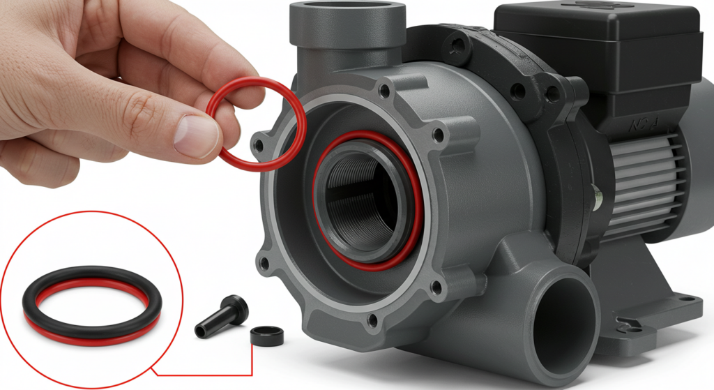
Proper alignment between a pump and its driving motor is a critical factor in ensuring reliable, efficient operation of the pumping system. Misalignment can lead to a host of issues including excessive vibration, premature bearing failure, and increased power consumption.
Achieving precise alignment involves a systematic process of measuring and correcting the relative positions of the pump and motor shafts. In this article, we will walk through the key steps to properly align a pump with its motor, from preparation and rough alignment to final dial indicator readings and documentation.
Step 1: Ensure Proper Mounting and Leveling
Before beginning the alignment process, the pump and motor must be properly mounted on a flat, rigid base or frame. Use a precision level to ensure both the pump and motor are sitting level in all directions.
Step 2: Connect Coupling Halves
The next step is to loosely connect the coupling halves between the pump and motor shafts. Leave the coupling bolts just loose enough so that the coupling faces can still move independently. This will allow you to measure misalignment between the two shafts. Be sure to follow the coupling manufacturer’s instructions regarding spacing between the coupling halves.
Step 3: Check Angular Alignment
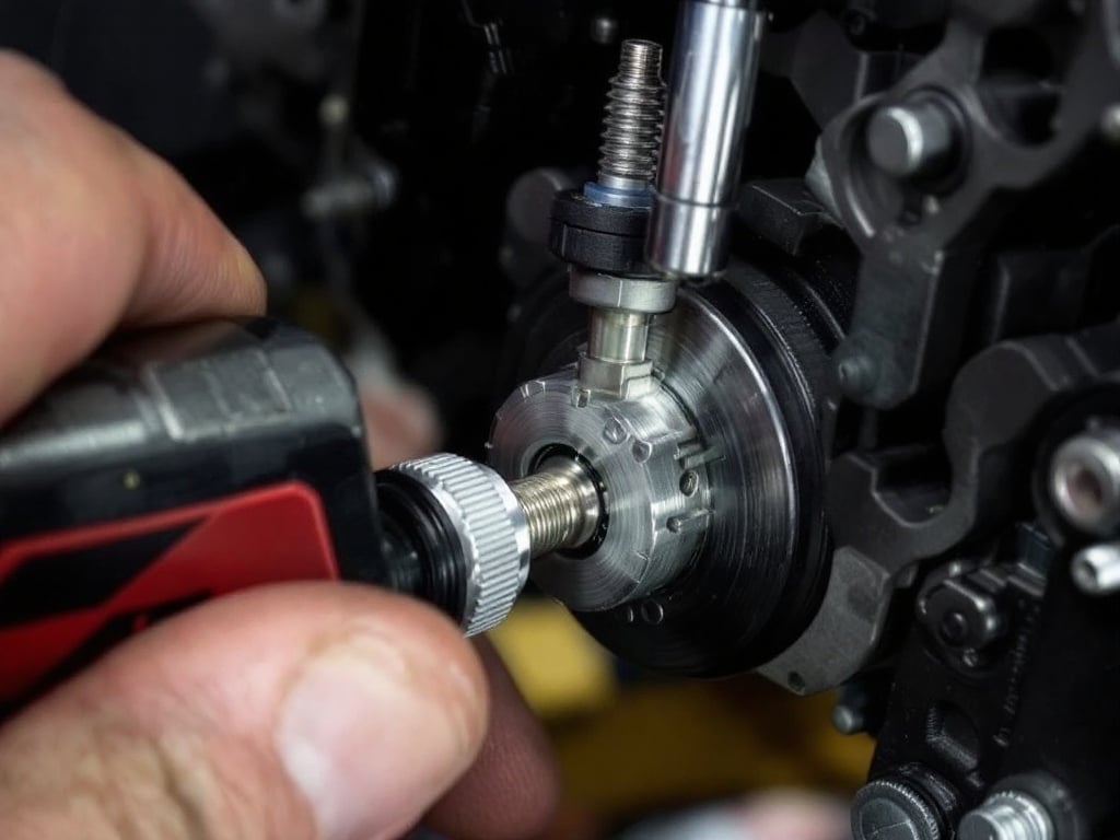
Angular misalignment occurs when the centerlines of the pump and motor shafts are not parallel. To check for angular misalignment, attach a dial indicator to one coupling half so that the indicator tip rests on the face of the opposite coupling half.
Rotate the shaft by hand and observe the indicator readings at the 12, 3, 6, and 9 o’clock positions. Adjust the motor position using shims until the difference in readings is within the acceptable tolerance specified by the manufacturer, typically 0.002-0.005 inches per inch of coupling diameter.
Step 4: Check Parallel Offset
Parallel misalignment occurs when the centerlines of the pump and motor shafts are parallel but not concentric. With the dial indicator still attached to one coupling half, move the indicator tip to the outside diameter of the opposite coupling half.
Again, rotate the shaft and note the readings at the four clock positions. Adjust the motor position laterally and vertically until the difference in readings falls within the acceptable range, usually 0.002-0.005 inches.
Step 5: Repeat Alignment Checks
After making adjustments for angular and parallel alignment, repeat the checks in steps 3 and 4. It may take several iterations to achieve acceptable alignment in both planes. Be patient and make small, incremental adjustments to avoid overcorrecting.
Step 6: Final Tightening and Verification
Once the alignment is within tolerance, tighten down the motor bolts to the torque specifications provided by the manufacturer. Then perform a final alignment check to verify nothing shifted during the tightening process. If alignment remains acceptable, securely tighten the coupling bolts per the manufacturer’s instructions. The pump and motor are now properly aligned and ready for operation.

