What Is Shaft Runout
Shaft runout refers to the deviation of a rotating shaft from its ideal centerline. This can occur in both radial and axial directions. Radial runout is the deviation perpendicular to the shaft’s axis, while axial runout is the deviation along the shaft’s axis. Excessive runout can cause vibration, reduced bearing life, and other issues.
How to Measure Shaft Runout
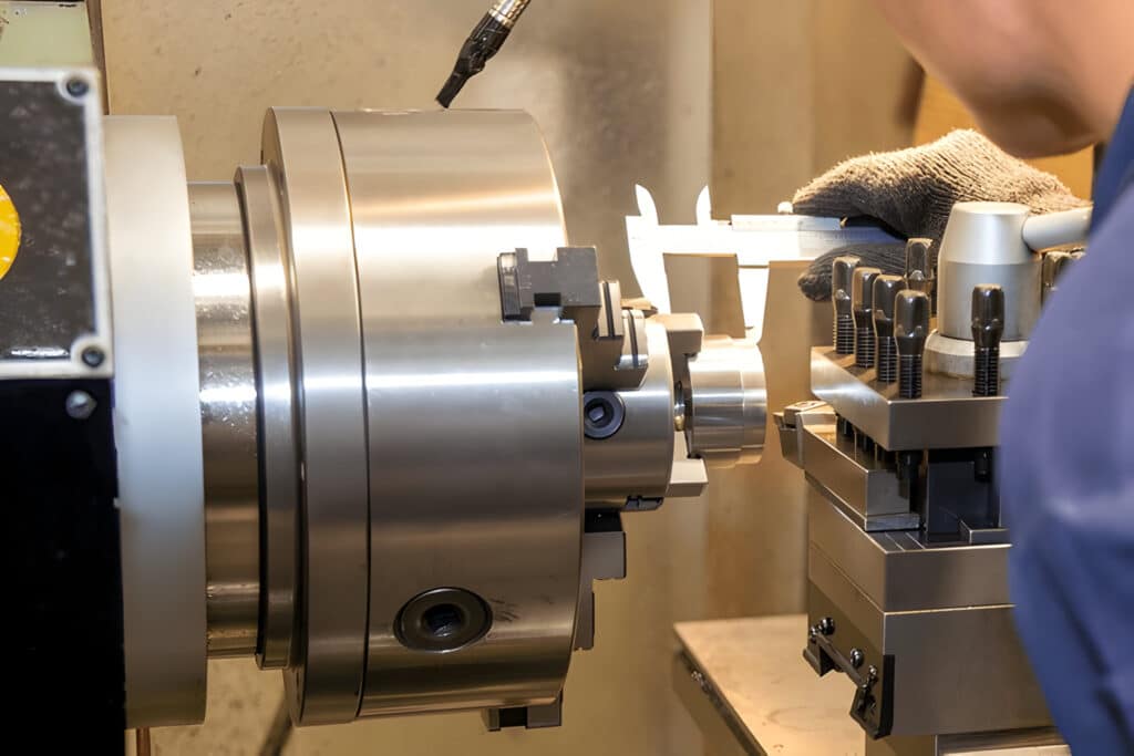
- Secure the shaft in a lathe or a suitable fixture.
- Set up a dial indicator with its plunger perpendicular to the shaft surface for radial runout or parallel to the shaft axis for axial runout.
- Rotate the shaft slowly, noting the maximum and minimum readings on the dial indicator.
- Calculate the total runout by subtracting the minimum reading from the maximum reading.
- Compare the total runout to the acceptable limits for your application.
How to Repair Shaft Runout
- Identify the high spot on the shaft using a dial indicator.
- Set up the shaft in a lathe or grinding machine.
- Carefully remove material from the high spot using turning or grinding operations.
- Recheck the runout with a dial indicator and repeat the process if necessary.
- Balance the shaft if required for high-speed applications.
Electrical vs Mechanical Runout
Electrical runout is the variation in the electrical signal generated by a shaft-mounted sensor due to shaft runout. This can lead to inaccurate readings and control issues.
Mechanical runout refers to the physical deviation of the shaft from its ideal centerline. Both types of runout can be problematic and should be minimized for optimal performance.
What Is Shaft Deflection
Shaft deflection is the bending or displacement of a shaft under applied loads. It can be caused by the shaft’s weight, external forces, or moments. The amount of deflection depends on factors such as the shaft material, cross-section, length, and support conditions. Excessive deflection can lead to misalignment, increased wear, and even structural failure.
How to Measure Shaft Deflection
- Set up the shaft in its operating position, including any supports or bearings.
- Apply the expected loads to the shaft, simulating real-world conditions.
- Measure the shaft deflection using dial indicators, laser sensors, or other suitable methods.
- Record the deflection at multiple points along the shaft to create a deflection profile.
- Compare the measured deflection to the allowable limits for your application.
How to Repair Shaft Deflection
- Identify the cause of excessive deflection (e.g., undersized shaft, inadequate supports).
- Modify the shaft design by increasing its diameter, changing its material, or optimizing its cross-section.
- Improve shaft supports by adding bearings, reducing span lengths, or adjusting preload.
- Recheck the shaft deflection under applied loads to verify the effectiveness of the modifications.
- Consider additional factors, such as critical speed and vibration, when making design changes.
What Is Shaft Whip
Shaft whip is a vibration phenomenon that occurs when a rotating shaft’s rotational speed exceeds its first critical speed. At this point, the shaft’s deflection increases dramatically, causing a whipping motion. This can lead to excessive vibration, noise, and even catastrophic failure if left unchecked.
How to Measure Shaft Whip
- Install vibration sensors at key locations along the shaft and on adjacent components.
- Gradually increase the shaft’s rotational speed while monitoring the vibration levels.
- Identify the critical speed at which shaft whip occurs, indicated by a sharp increase in vibration.
- Record the vibration frequency, amplitude, and phase information for further analysis.
- Compare the measured vibration levels to acceptable limits for your application.
How to Repair Shaft Whip
- Identify the root cause of shaft whip (e.g., unbalance, misalignment, bearing issues).
- Balance the shaft to reduce vibration excitation forces.
- Align the shaft and its components to minimize misalignment-induced vibration.
- Inspect and replace bearings if necessary to ensure proper support and damping.
- Modify the shaft design to increase its critical speed, such as by changing its diameter, material, or support conditions.
- Retest the shaft to verify that the whip has been eliminated or reduced to acceptable levels.
FAQs
How Much Shaft Runout Is Acceptable?
Generally, for high-speed or precision applications, total runout should be limited to a few microns (µm). In contrast, for lower-speed or less critical applications, runout tolerances may be more relaxed, allowing for tens or even hundreds of microns.
