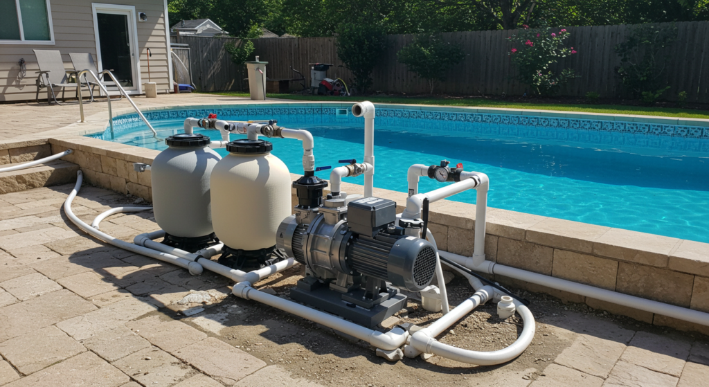
Misaligned pumps are a costly and common issue in industrial facilities, leading to excessive vibration, leakage, and premature component failure. Improper alignment wastes energy, increases maintenance costs, and can cause expensive downtime.
Ignoring pump misalignment puts your equipment and bottom line at risk. Misaligned shafts experience up to 6x more strain, drastically reducing bearing life. Even small alignment issues compound over time, resulting in catastrophic failures if left unchecked.
In this guide, we’ll cover the types of misalignment, proven methods to precisely align pump shafts, and step-by-step instructions to keep your pumps running smoothly.
What is Pump Alignment
Pump alignment is the process of precisely positioning and orienting the rotational centerlines of a pump and its driving unit (such as an electric motor) to minimize misalignment between the two machines. Proper alignment ensures that the shafts of the pump and motor are coaxial, meaning their centerlines are in a straight line, both horizontally and vertically.
Types of Pump Misalignment
Radial Misalignment
Radial misalignment, also known as offset misalignment, occurs when the centerlines of the pump and driver shafts are parallel but not concentric. This type of misalignment can cause uneven loading on bearings and seals, leading to premature wear and failure. Radial misalignment is typically caused by improper installation or foundation settling.
Axial Misalignment
Axial misalignment, or end-float, refers to the condition where the pump and driver shafts are concentric but not parallel. This misalignment occurs when there is an excessive gap or insufficient gap between the coupling faces. Axial misalignment can result in thrust loads on bearings, causing premature failure and increased vibration.
Angular Misalignment
Angular misalignment is characterized by the pump and driver shafts being neither parallel nor concentric. In this case, the shafts are at an angle to each other. Angular misalignment can cause uneven wear on coupling components, increased vibration, and premature bearing failure. This type of misalignment is often caused by improper installation, foundation settling, or thermal expansion.
Methods of Pump Alignment
Straight Edge and Feeler Gauge Method
The straight edge and feeler gauge method is a basic alignment technique that involves placing a straight edge across the coupling halves and using feeler gauges to measure the gap between the straight edge and the coupling faces. This method is relatively simple but lacks the precision of more advanced techniques. It is best suited for rough alignment or as a preliminary step before employing more accurate methods.
Dial Indicator Method
The dial indicator method uses two dial indicators, one mounted on each shaft, to measure the relative position of the shafts at various points along their circumference. This method provides more accurate results than the straight edge and feeler gauge technique. Dial indicators can measure both radial and axial misalignment, allowing for a more comprehensive alignment process.
Laser Alignment Systems
Laser alignment systems are the most advanced and accurate method for aligning pump and driver shafts. These systems use laser transmitters and receivers to measure the relative position of the shafts with a high degree of precision. Laser alignment allows for real-time monitoring of the alignment process, making it easier to make adjustments and achieve optimal alignment. While laser alignment systems are more expensive than other methods, they offer the highest level of accuracy and efficiency.
How to Align Shafts
STEP 1: Preparation
Before beginning the alignment process, ensure that the pump and motor are disconnected from power sources and the coupling is removed. Clean the shaft ends, coupling faces, and alignment tools to remove any dirt or debris that could interfere with accurate measurements. Inspect components for any visible damage or wear that may require replacement before proceeding.
STEP 2: Rough Alignment
Perform a rough alignment by using a straight edge and feeler gauges or a laser alignment system. Place the straight edge across the coupling halves at 90° intervals and use feeler gauges to measure any gaps between the straight edge and coupling faces. Adjust the motor position until the gap measurements are within the pump manufacturer’s specified tolerances.
STEP 3: Fine Alignment
For more precise alignment, use dial indicators or a laser alignment system. Mount a dial indicator on one shaft and position the indicator tip against the other shaft. Rotate both shafts simultaneously and note the indicator readings at 90° intervals. Adjust the motor position until the indicator readings are within the specified tolerances at all positions. Repeat this process in both the vertical and horizontal planes to correct for angular and parallel misalignment.
STEP 4: Confirm Alignment
After completing the fine alignment, recheck the measurements to confirm that the shafts are properly aligned. Rotate the shafts again and verify that the dial indicator readings remain within tolerance at all positions. If necessary, make minor adjustments to ensure optimal alignment.
STEP 5: Final Steps
Once the alignment is confirmed, reinstall the coupling and any guards or safety devices. Reconnect the pump and motor to their power sources. Start the pump and monitor for any unusual vibration, noise, or heat buildup during operation. Perform a final alignment check after the pump has reached normal operating temperature to account for any thermal expansion that may have occurred.
Common Issues Associated with Pump Misalignment
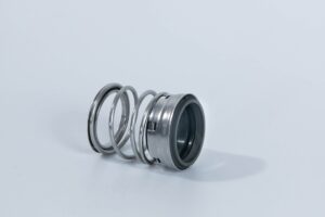
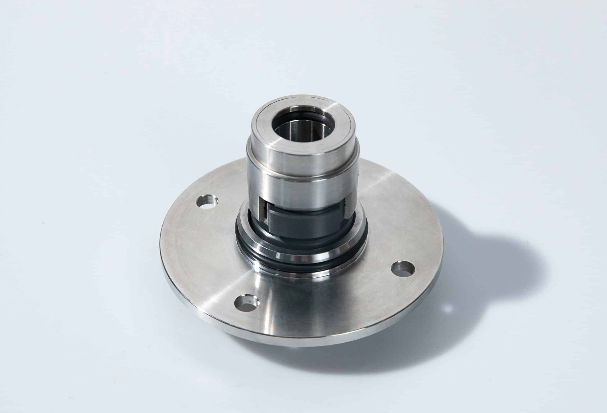
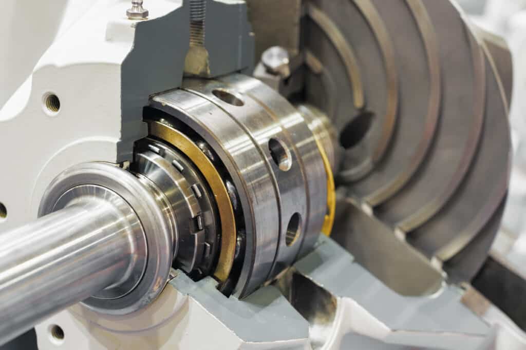
- Premature Component Failure: When a pump is misaligned, additional stresses are placed on bearings, mechanical seals, couplings, and shafts. The increased loads accelerate wear and fatigue, causing these critical components to fail prematurely.
- Excessive Vibration and Noise: Misaligned pumps tend to operate with significantly higher vibration levels compared to properly aligned units. The imbalance of forces within the pump and the greater movement of components generates strong vibrations that can be felt and heard throughout the system.
- Increased Power Consumption and Reduced Efficiency: To continue operating under misaligned conditions, pumps require greater input power to overcome the additional friction and drag forces. However, much of this extra energy is wasted as heat rather than contributing to useful pumping work.
- Excessive Leakage from Mechanical Seals and Gaskets: Misalignment can prevent mechanical seals from maintaining proper contact, resulting in an uneven seal face and greater leakage. Gaskets are also strained and deformed by the imbalance of forces, breaking their tight seals over time.
- Increased Maintenance Requirements and Costs: As misaligned pumps experience more breakdowns, more frequent repairs and part replacements become necessary. Both planned and unplanned maintenance tasks must occur more often to keep the pump operational.
- Fractures in Pump Casing and High Cycle Fatigue: Severe misalignment can place pump casings under extreme stress, leading to cracking and complete fracture. Excessive vibration and unbalanced forces may also cause pump impellers to impact the casing, gradually causing damage.
- Strain on Piping and Shifting of Baseplates: The forces generated by misaligned pumps are transferred directly into the attached piping. Pipes may bend, buckle, or rupture if the strain exceeds their pressure rating and material strength. Misalignment also shifts the pump assembly on the baseplate, altering the support points and force distribution.