What Is Plan 53a
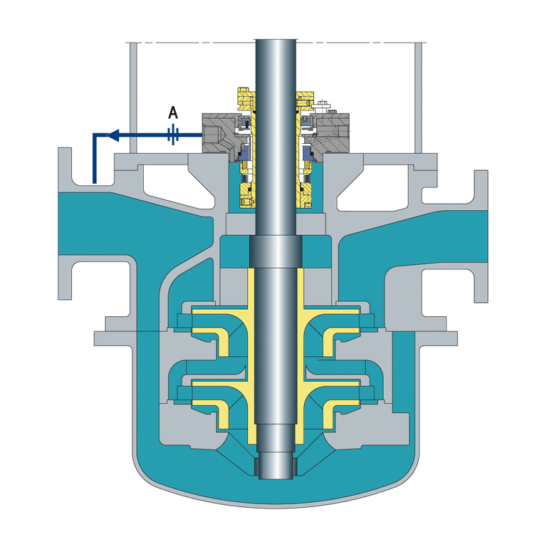
Plan 53a (API Plan 53A) is a mechanical seal support system that provides a pressurized barrier fluid to the seal cavity. This barrier fluid maintains a higher pressure than the process fluid, preventing process fluid from entering the seal cavity and causing damage to the seal faces. The barrier fluid is typically a clean, compatible liquid that is maintained at a pressure at least 20 psi (1.4 bar) above the seal chamber pressure.
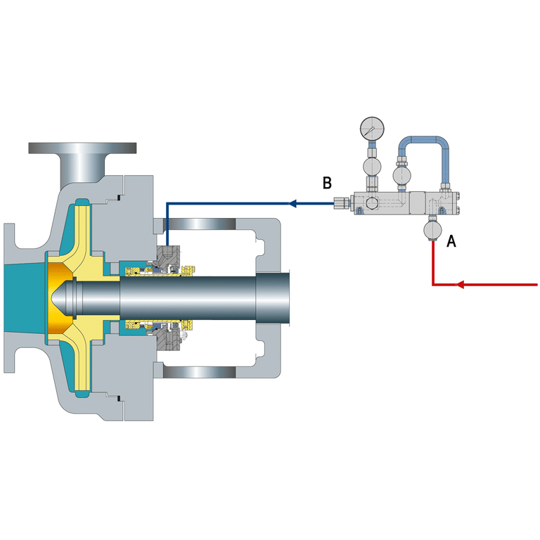
In a Plan 53a system (API 53A), the barrier fluid is supplied from a reservoir whose gas space is pressurized directly by a nitrogen bottle or plant instrument gas supply. The pressurized reservoir is connected to the seal cavity through a series of valves and piping, allowing the barrier fluid to flow into the seal cavity and maintain the desired pressure differential. Within the API 682 / API 610 family of API seal plans, the 53-series provides pressurized barrier fluid support for dual mechanical seal arrangements where process leakage to atmosphere is unacceptable.
Advantages of 53a
- Simple, low-cost design with few moving parts — the lowest capital cost of the three Plan 53 variants.
- Large reservoir volume (typically 3-5 gallons) allows wear particles to settle out of circulation, which is mechanically forgiving at pressures where both 53A and 53B would work.
- Direct gas pressurization of the reservoir, with no bladder or piston, simplifies pressure control.
- Adequate cooling for most moderate-temperature applications from a coil inside the reservoir, without an external heat exchanger.
- Well suited to protecting a single dual-seal arrangement on clean, non-condensing process fluids.
Disadvantages of 53a
- Limited pressure range: Plan 53a is typically capped at 10.34 bar (150 psig) seal chamber pressure for reliable operation, with some vendor literature citing 300 psig as a hard ceiling; above 150 psig, 53B is preferred.
- Nitrogen entrainment: because the pressurizing gas contacts the barrier fluid directly, nitrogen dissolves into the fluid at elevated pressure, reducing lubricity at the seal faces and accelerating wear — a failure mode that 53B eliminates via the bladder interface.
- Limited cooling: Plan 53a cools only through a coil inside the reservoir, which limits it in high-temperature or high-heat-load services where Plan 53c (dedicated heat exchanger) is more appropriate.
- Continuous gas header dependency: Plan 53a requires a constant plant nitrogen or instrument gas supply, making it awkward for remote installations where no gas header is available. Higher susceptibility to gas absorption into the barrier fluid over time; requires periodic barrier fluid condition checks.
When to Use 53a
Plan 53a is the default choice when seal chamber pressure stays at or below 10.34 bar (150 psig), the process fluid is clean and non-condensing, a single dual-seal arrangement is being protected, plant nitrogen or instrument gas is continuously available, and cost is the primary driver. In these conditions, 53A’s simple design and forgiving reservoir volume usually outperform more complex alternatives.
What Is Plan 53b
API Plan 53b is a seal plan designed for dual pressurized seals using a bladder-type accumulator that is pre-charged with inert gas (no external gas header required during normal operation). The accumulator supplies pressurized barrier fluid to the seal cavity, where it maintains a pressure higher than the process fluid and prevents process leakage across the inner seal. This plan is the standard choice when seal chamber pressures are between 10.34 bar and 51.71 bar (150-750 psig) or when gas entrainment from a 53A header is unacceptable.
In Plan 53b (API Plan 53B), the barrier fluid is typically a clean, compatible liquid that is immiscible with the process fluid. The bladder accumulator’s pre-charge pressure and sizing together determine the refill interval — with proper sizing, a single pressurization can sustain the system for 28 days or longer. A pressure transmitter with a temperature-biased alarm monitors the accumulator, ensuring that both fluid volume and barrier pressure remain within the acceptable range.
Advantages of 53b
- Higher pressure capability than 53A (no gas-entrainment pressure limit) and suitable for the 150-750 psig operating window where 53A becomes unreliable.
- Bladder accumulator keeps gas and barrier fluid on opposite sides of the bladder, eliminating nitrogen entrainment into the fluid — the dominant failure mechanism at elevated pressures in 53A.
- One-time pressurization plus a minimum 28-day refill interval makes 53B suitable for remote or no-nitrogen-header installations where 53A is impractical.
Disadvantages of 53b
- Small barrier fluid volume (typically 15-25% of a 5- or 9-gallon accumulator) recirculates wear particles continuously through the seal chamber with no opportunity to settle, which can damage seal faces over time.
- Higher capital cost than 53A due to the bladder accumulator assembly and its instrumentation.
- Requires periodic pre-charge pressure checks and bladder inspection; loss of pre-charge silently degrades barrier pressure.
When to Use 53b
Plan 53b is the right choice when seal chamber pressure falls between 10.34 bar and 51.71 bar (150-750 psig), when nitrogen entrainment in a 53A reservoir would degrade barrier fluid lubricity, when the installation is remote or lacks a continuous nitrogen header, or when a single support system must feed several dual-seal pumps.
What Is Plan 53c
Plan 53c (API Plan 53C) is a between-seals pressurized support system for dual mechanical seals in which barrier-fluid pressure is generated by a piston pressure intensifier driven by the pump’s own process pressure — not by an external nitrogen header and not by a cyclone separator. A reference line ties one face of a stepped piston to the seal chamber (or to discharge, for low-pressure pumps); the opposite, smaller face pressurizes the barrier fluid.
Because the two piston face areas are unequal, the output barrier pressure is a multiple of the reference pressure, set by the area ratio A1/A2. Typical practical ratios fall in the 1.05-1.30 range, but the ratio must be chosen with the reference pressure so barrier pressure clears API 682’s minimum differential of 1.4 bar (20 psi), rising to about 1.5 at low reference pressures.
The system is self-energizing: it tracks fluctuations in seal chamber pressure automatically and needs no external utility (no plant nitrogen, no dedicated charge pump) to maintain the required barrier differential. Piston ratio selection follows seal chamber pressure range — 4-10 bar typically uses a 1:1.5 ratio, 10-22 bar a 1:1.2 ratio, and 22-40 bar a 1:1.1 ratio. API 682 4th Edition (2014) Annex G specifies Plan 53C under the between-seals pressurized dual seal category.
Advantages of 53c
- Pressure-tracking output: barrier pressure is amplified from the seal chamber or discharge reference, so a fluctuating process pressure is followed automatically with a fixed differential — the one scenario where 53A and 53B cannot match 53C.
- No external utilities: the piston intensifier is driven by the pump’s own pressure, so no plant nitrogen header, instrument gas, or charge pump is required.
- Compact accumulator footprint compared with a full barrier or buffer reservoir, useful where plot space is tight.
- Standard support for multiple seal arrangements; barrier pressure is tied directly to process reference, making the differential deterministic.
Disadvantages of 53c
- Highest capital cost of the three Plan 53 variants due to the piston intensifier’s machined tolerances.
- Strictly a clean-fluid application — fine abrasives or suspended solids damage the piston seal and cylinder walls; solidifying fluids plug the reference line as it cools.
- Least standardized of the three; 53C is generally considered less field-reliable than 53A or 53B, and practitioner accounts report more periodic maintenance than reservoir or bladder accumulator designs.
- Low-pressure pumps cannot use the seal chamber as reference; final discharge or an intermediate stage must be tapped, adding piping complexity.
When to Use 53c
Plan 53c is reserved for applications where the seal chamber pressure fluctuates and the barrier-to-process differential must be maintained inside a narrow, tracked band, where plant nitrogen is unavailable or undesirable, and where the process and barrier fluids are clean enough to protect the piston seal. Typical fits include high-pressure refining services with variable suction conditions and critical dual-seal arrangements where a utility-free, self-energizing barrier is preferred.
Differences between Seal Plan 53a, 53b and 53c
The three Plan 53 systems (53A, 53B, 53C) differ primarily in how barrier fluid pressurization is achieved. Plan 53 is an API 682 pressurized barrier fluid support plan with three variants — 53A, 53B, and 53C — distinguished by how pressure is generated and maintained.
| Feature | Plan 53a | Plan 53b | Plan 53c |
|---|---|---|---|
| Pressure Range | Up to ~10.34 bar (150 psig) | ~10.34-51.71 bar (150-750 psig) | High / tracks reference, 4-40 bar typical |
| Barrier Fluid Reservoir | Gas-pressurized seal pot (no bladder) | Bladder accumulator (5 or 9 gal by shaft size) | Piston intensifier cylinder |
| Pressure Source | Reservoir gas cap, externally pressurized (gas bottle or plant gas) | Bladder-type accumulator, pre-charged with inert gas | Piston pressure amplifier (intensifier) driven by process pressure |
| Gas/Fluid Separation | None — gas contacts fluid directly | Bladder separates gas and fluid | No gas; hydraulic amplification only |
| Cooling | Reservoir cooling coil | Heat exchanger in circulation loop | Heat exchanger in circulation loop |
| Particulate Sensitivity | Tolerant — large reservoir lets wear particles settle | Sensitive — small volume recirculates particles | Intolerant — piston seal damaged by abrasives |
| Number of Seal Systems Supported | Typically one dual-seal arrangement | Multiple pumps from one system | Typically one dual-seal arrangement, tight differential |
| Utility Requirement | Continuous plant nitrogen / gas header | One-time pre-charge; ≥28 day refill interval | None — self-energizing from process |
| Cost | Lowest | Moderate | Highest |
Selection Decision: Matching Plan 53A/B/C to Process Pressure and Barrier Fluid Requirements
Start with pressure, then layer the constraints on top. If seal chamber pressure stays at or below 10.34 bar (150 psig), the process fluid is clean, a continuous plant nitrogen header is available, and cost is the primary driver, Plan 53A is the default — its large reservoir also helps wear particles settle out of circulation, which is actually more forgiving than 53B where both are viable.
If pressure climbs into the 150-750 psig band, if nitrogen entrainment into the barrier fluid is a real concern, if the installation is remote with no gas header, or if several pumps must share one support system, step up to Plan 53B — the bladder accumulator and 28-day refill interval handle these cases cleanly.
Reserve Plan 53C for the narrower niche it is designed for: a fluctuating seal chamber pressure where the barrier differential must track inside a narrow, fixed band (self-energized, no external utility), with clean process and barrier fluids to protect the piston seal, and when a cost premium and tighter maintenance schedule are acceptable. In practice, most dual-seal pressurized applications resolve to 53A or 53B; 53C is the answer only when a tracked-differential, utility-free behavior is explicitly required.