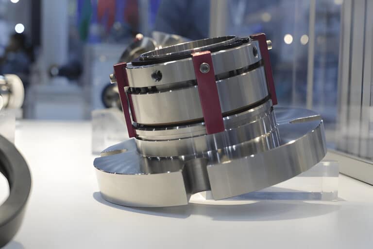
A seal with a 0.008-inch defect passes the standard API 682 air integrity test — then leaks 270 to 1,300 times the allowable rate when it hits liquid service. The difference between pass and fail wasn’t the seal. It was the test fixture volume: 28 liters of dead air space absorbed the pressure drop that should have flagged the defect.
Before you blame the seal, check your test setup. I’ve condemned more good seals over bad fixtures than I’ve ever rejected for actual manufacturing defects. The procedures and acceptance criteria below will help you test mechanical seals correctly — and just as importantly, avoid the setup errors that produce misleading results.
Pre-Test Preparation and Fixture Setup
I worked on a North Sea project that analyzed recurring seal failures across 40 pumps. The root causes weren’t the seals — they were installation variance and unclear acceptance criteria. Testing follows the same pattern. A sloppy fixture produces sloppy results.
Visual and Dimensional Checks
Before mounting any seal in a test fixture, run through these checks:
- Inspect seal faces under magnification for chips, scratches, or contamination. Dirt on a seal face — even oil from fingerprints — sets it up to fail. Handle faces with lint-free gloves only.
- Verify critical dimensions against the assembly drawing: seat diameter, spring length at free height, and gland pilot fit. A dimensional mismatch creates a false leak path that has nothing to do with seal quality.
- Check O-rings and secondary seals for nicks, flat spots, or swelling. If they spin dry against a shaft surface for even one second during installation, replace them — the heat damage is invisible but permanent.
Fixture Volume and Configuration
This is where most test failures originate. The API 682 integrity test allows a maximum reservoir volume of 28 liters. At that volume, a 0.008-inch orifice defect produces exactly 2 psi of pressure drop over five minutes — right at the pass/fail threshold. The same defect tested in a 1.5-liter volume produces 22 psi of pressure drop. Same seal, same defect, 11 times the signal.
A properly manufactured seal shows zero pressure drop in the 1.5-liter configuration. The lesson is straightforward: if your test fixture has excess volume — long piping runs, oversized reservoirs, air pockets in dead legs — you are diluting the sensitivity of every test you run.
Before you test a single seal, test your fixture. Pressurize it with all ports capped and no seal installed. If it holds pressure for the full test duration, your fixture is tight. If it doesn’t, fix the fixture before touching a seal.
The Air Integrity Test (API 682)
The API 682 integrity test has been the industry standard assembly verification tool since 1994. It catches manufacturing defects and assembly errors — but it does not predict operational performance.
Pressurize the seal assembly with clean, dry air to 1.7 barg (25 psig) in a maximum 28-liter volume. Hold for a minimum of five minutes. The maximum allowable pressure drop is 0.14 bar (2 psi). That threshold corresponds to a face separation of 4 to 6 microns and an equivalent air leakage rate of 56.9 g/hr.
A seal that passes this test is correctly assembled. It is not guaranteed to perform in service. The integrity test uses one standard regardless of seal arrangement, materials, face technology, or size. High-pressure seals with low balance ratios may seal liquids perfectly but leak air. Polished-face seals show less air leakage than lapped-face alternatives with identical sealing performance. If you get a borderline failure on a seal design that doesn’t favor air testing, retest with the fixture volume minimized before condemning it.
API 682 defines three distinct test categories. The Qualification Test demonstrates performance in specific fluid groups over extended duration. The Integrity Test verifies assembly only. The Hydrostatic Test checks glands and reservoirs for structural integrity. Most shop-floor testing is integrity testing — know what it tells you and, more importantly, what it doesn’t.
Hydrostatic and Dynamic Run Tests
The integrity test catches assembly problems. Hydrostatic and dynamic tests catch everything else.
Hydrostatic Pressure Test
Hydrostatic testing applies to seal glands, reservoirs, and piping systems — not the seal faces themselves. Fill the assembly with liquid (typically water or test oil), pressurize to a minimum of 1.5 times rated pump pressure, and hold for at least 30 minutes. Watch for weeping at gasket joints, gland bolt connections, and piping fittings.
The ASME Pressure Vessel Code has already lowered the hydrostatic test ratio from 1.5 to 1.3 for Section VIII vessels. Even so, 1.5 times remains the standard for most seal system components. If your customer spec calls out a different ratio, follow their document — not the default.
Dynamic Run Test
Static tests verify that the seal is built correctly. Dynamic run tests verify that it works. Mount the seal on a test bench capable of running at the intended operating speed, pressure, and temperature. Industrial test benches typically cover atmospheric to 40 bar, room temperature to 150 C, and speeds from 0 to 4,200 rpm.
Start the test with the process fluid (or a suitable surrogate) circulating through the seal chamber. Never run a seal dry during testing — seal faces can overheat and disintegrate in as little as 30 seconds without lubrication. Monitor leakage, temperature, and vibration over a minimum 30-minute stabilization period. Acceptable leakage during dynamic run testing depends on the seal type, fluid, and customer specification, but any visible drip-rate leakage on a new seal is cause for investigation.
The most common mistake I see is skipping the dynamic test because the seal “passed air.” An air test at 25 psi tells you nothing about how the seal handles 15 bar of hot process fluid at 3,600 rpm.
The 4-Test Protocol: What to Run and When to Stop
Not every seal needs every test. Running all four tests on every seal wastes time; skipping the wrong test destroys reliability. Here is the protocol I follow:
Test 1 — Visual and Dimensional Inspection. Every seal, every time. This catches shipping damage, wrong components, and contamination before anything touches a fixture. If it fails here, stop — no point pressurizing a dimensionally wrong assembly.
Test 2 — Air Integrity Test. Every new or rebuilt seal before installation. This is your assembly verification gate. If it fails, disassemble, inspect, and reassemble before retesting. Do not skip to hydrostatic testing to “see if liquid seals better” — that logic is backwards.
Test 3 — Hydrostatic Test. Required for seal support systems (glands, reservoirs, piping) and for any application where the customer specification calls it out. Not required for the seal faces themselves on standard single-seal installations.
Test 4 — Dynamic Run Test. Required for engineered seals, dual seals, and any critical-service application. For standard single seals going into non-critical pumps, this test is often skipped in the field — but if you have access to a test bench, run it. The 30-minute dynamic test catches problems that no amount of static testing reveals.
Factory vs. field testing: Factory acceptance testing typically includes all four steps. Field verification after installation focuses on visual inspection, a brief static pressure check with bubble detection (5-10 psi air with soapy water on the seal area), and monitoring during initial startup. Cartridge seals simplify field testing because the seal is pre-assembled and pre-set — you are verifying the installation, not the seal itself.
When Tests Fail: Diagnosis Before Rejection
A failed test does not automatically mean a bad seal. In my experience, up to a quarter of seal failures trace back to installation errors, and another 13% link to bearing condition — problems the seal never caused and testing alone won’t fix.
When a seal fails any test, resist the instinct to grab a new seal. Instead, work through this sequence:
- Check the fixture first. Pressurize the fixture without the seal. If it leaks, you have a fixture problem, not a seal problem.
- Inspect secondary seals. O-ring damage from installation — a pinched O-ring, a twisted gasket, a dry elastomer that caught on a sharp edge — accounts for the majority of false test failures I see.
- Distinguish primary from secondary symptoms. A groove on the seal face is a primary symptom — direct evidence of a failure cause. Carbon deposits on the sleeve are secondary — they resulted from the groove, not the other way around. Chasing secondary symptoms sends troubleshooting in the wrong direction.
- Retest before rejecting. If the fixture checks out and secondary seals look good, reassemble the seal with fresh O-rings and retest. I’ve watched technicians condemn expensive cartridge seals that passed perfectly on the second attempt after a careful reassembly.
When a seal genuinely fails — consistent leakage through the faces after fixture and procedure variables are eliminated — document the failure mode before returning it. Photograph the seal faces, note the test conditions, and record the measured leak rate. That documentation is what separates a warranty claim from an argument. If the leak persists after proper reassembly, move to troubleshooting the root cause before ordering a replacement.
Next Steps
Test your test rig before you test the seal. Minimize fixture volume, verify fixture integrity with a blank pressurization, and handle seal faces like precision instruments. Follow the 4-test protocol: visual, air integrity, hydrostatic where required, and dynamic run for anything critical. When results look wrong, check your setup before you condemn the seal. The most expensive mistake in seal testing is replacing a good seal because a bad fixture said it failed.