Axial thrust, a critical factor in centrifugal pump design and operation, refers to the net force acting parallel to the pump shaft. This article delves into the causes, consequences, and management strategies for axial thrust in centrifugal pumps, providing valuable insights for engineers and pump users alike.
Key Components Contributing to Axial Thrust
- Axial hydraulic forces on the impeller shrouds: The pressure distribution on the front and back shrouds of the impeller creates an axial force.
- Momentum forces from change in fluid axial velocity: As the fluid accelerates or decelerates in the axial direction, it exerts a force on the impeller, contributing to axial thrust.
- Forces from pressure differences across seals and bearings: Pressure imbalances across shaft seals and bearings can generate additional axial forces on the pump rotor.
- Weight of rotor components (for vertical pumps): In vertical pump configurations, the weight of the rotor assembly, including the impellers, shaft, and other components, contributes to the overall axial thrust.
Equation for Calculating Axial Thrust
The axial thrust (F) acting on a centrifugal pump impeller can be calculated using the following equation:
F = (P1 – P2) × A + ρ × Q × (V2 – V1)
Where:
- P1 and P2 are the pressures acting on the front and back shrouds of the impeller, respectively
- A is the area of the impeller shroud
- ρ is the fluid density
- Q is the volumetric flow rate
- V1 and V2 are the axial velocities of the fluid at the inlet and outlet of the impeller, respectively
This equation accounts for both the pressure forces and the momentum forces acting on the impeller in the axial direction.
Causes of Axial Thrust in Different Pump Designs
Single-stage Pumps
In single-stage centrifugal pumps, axial thrust primarily arises from the pressure difference between the front and back shrouds of the impeller. The higher pressure on the discharge side of the impeller creates a net force that pushes the impeller towards the suction side. This axial thrust can be influenced by factors such as impeller design, operating conditions, and wear ring clearances.
Multistage Pumps
Multistage centrifugal pumps, which feature multiple impellers arranged in series, face additional challenges in managing axial thrust. The pressure increases across each stage compound, resulting in a significantly higher axial force compared to single-stage pumps. In addition, the presence of balance drums, balance discs, or balance pistons, which are used to counteract axial thrust, introduces additional complexity to the system.
Consequences of Excessive Axial Thrust
- Overloading and premature failure of thrust bearings: High axial forces can cause thrust bearings to operate beyond their rated capacity, leading to accelerated wear and premature failure.
- Excessive shaft deflection and vibration: Unbalanced axial forces can cause the pump shaft to deflect, resulting in increased vibration levels and reduced bearing life.
- Accelerated wear of pump internal clearances: Axial thrust can cause contact between rotating and stationary components, such as wear rings and balance drums, leading to accelerated wear and increased clearances.
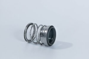
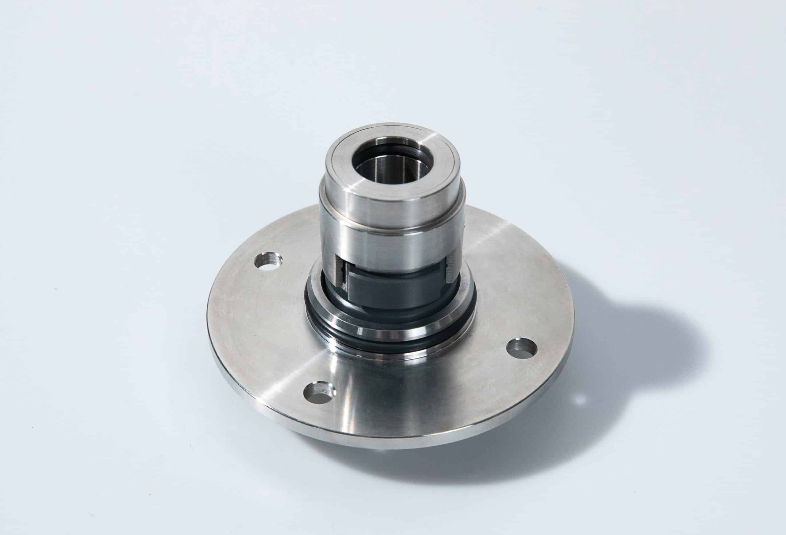
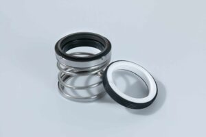
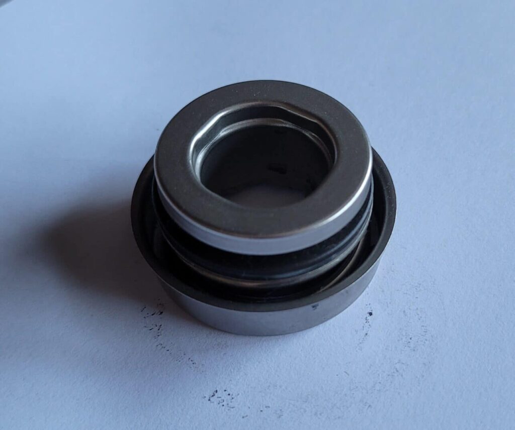
- Mechanical seal leakage and failure: Excessive axial movement of the pump rotor can cause mechanical seals to leak or fail prematurely.
- Reduced pump efficiency and reliability: The combined effects of increased vibration, wear, and component damage due to excessive axial thrust can significantly reduce pump efficiency and overall reliability.
Methods for Balancing and Controlling Axial Thrust
- Thrust bearings and their sizing: Properly sized and selected thrust bearings, such as angular contact ball bearings or tilting pad bearings, can effectively support the axial loads generated by the pump. Careful consideration must be given to the bearing’s load capacity, speed rating, and lubrication requirements.
- Impeller arrangements: The use of double suction impellers or back-to-back impeller arrangements can help balance the axial forces acting on the pump rotor, reducing the net axial thrust.
- Balance drums, discs, and pistons: These devices, mounted on the pump shaft, create a counter-acting axial force by utilizing the pressure difference between the pump discharge and suction.
- Balancing holes and counter-vanes on impellers: Strategically placed holes or counter-vanes on the impeller shrouds can help equalize the pressure distribution, reducing the net axial force acting on the impeller.
- Automatic hydraulic balancing devices: Self-adjusting hydraulic balancing devices, such as the ITT Goulds Pumps “Balanced-Flow” system, can automatically maintain optimal axial thrust balance under varying operating conditions.
- Effect of wear ring clearances: Maintaining proper wear ring clearances is essential for controlling axial thrust. As wear ring clearances increase due to normal wear, the pressure distribution around the impeller changes, potentially increasing axial thrust.
FAQs
What is the difference between axial and radial thrust bearings?
Axial (thrust) bearings are designed to support loads acting parallel to the shaft axis, while radial bearings support loads acting perpendicular to the shaft axis.
In centrifugal pumps, axial thrust bearings are used to counteract the axial forces generated by the pump impellers and pressure distribution within the pump casing. Radial bearings support the weight of the pump rotor and any radial forces arising from impeller-casing interactions or shaft misalignment.
Conclusion
Understanding and effectively managing axial thrust is crucial for ensuring the reliable and efficient operation of centrifugal pumps. By considering the various factors that contribute to axial thrust, such as impeller design, pump configuration, and operating conditions, engineers can design and select appropriate thrust balancing strategies.
Regular monitoring, maintenance, and adherence to operational best practices can further help minimize the impact of axial thrust on pump performance and longevity.
