If you’ve ever dealt with a leaking pump or watched equipment fail prematurely, you’ve likely experienced the consequences of poor shaft tolerance. I learned this the hard way. When our maintenance team rushed an installation without verifying shaft runout, we lost a critical seal within three weeks—and the equipment was down for costly repairs. That single mistake could have been prevented with a simple dial indicator measurement.

What Is Shaft Tolerance and Why Does It Matter?
Shaft tolerance refers to the allowable variation in shaft diameter from the ideal dimension. Instead of a shaft being exactly 25 millimeters, for example, it might be specified as 25mm +0.000/-0.006mm. That range—the allowable deviation—is the tolerance.
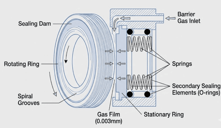
Why does this matter? Mechanical seals are precision instruments with extremely close tolerances themselves. They maintain a seal through controlled contact between two precision faces: one rotating with the shaft and one stationary. If the shaft diameter varies too much from specification, the seal loses its proper fit. The seal can rotate too loosely on the shaft, causing leakage, or too tightly, creating excessive friction and heat.
But shaft tolerance is about more than just diameter. It’s also about how much the shaft wobbles during rotation—a measurement called runout. Runout is where most tolerance problems show up in real-world applications.
Think of it like this: imagine trying to balance a spinning wheel that’s slightly warped. The wobble puts stress on one side, creates gaps on the other, and generally makes everything worse. That’s what excessive shaft runout does to a mechanical seal. The seal faces can’t maintain consistent contact, the pressure balance gets disrupted, and leakage happens.
Understanding Industry Standards for Shaft Tolerance
The good news is that mechanical seals don’t operate in a standards vacuum. Industry has established clear specifications that tell you exactly what shaft tolerance you need.
The primary standard is ISO 286-2, which defines the system of tolerances and fits for shafts globally. For mechanical seals specifically, the standard tolerance class is h11. You’ll see this notation on engineering drawings across the industry. It means the shaft diameter tolerance is tightly controlled but achievable with standard manufacturing processes.
Different applications have different requirements. DIN 3760 and DIN 3761 are German standards that specify rotary shaft seals and seal system combinations. These standards define not just shaft diameter tolerances but also surface finish, material hardness, and runout limits. If you’re working with European equipment or manufacturers, these standards are your reference.
In the petroleum and chemical industries, API 610 and API 682 are the go-to standards. API 610 covers the design and construction of centrifugal pumps, while API 682 provides detailed requirements for shaft sealing systems. These standards reference the tolerance requirements and ensure consistency across the industry.
Surface finish is integral to tolerance specifications. A shaft can be manufactured to the right diameter but with a rough, damaged surface that destroys the seal. Standard surface finish requirements range from 0.4 to 0.8 micrometers Ra (that’s 16 to 32 microinches Ra in imperial units). Some precision applications require even smoother finishes—down to 0.2 micrometers Ra or better. The smoother the surface, the better the seal performs and the longer it lasts.
Shaft Runout: The Critical Tolerance Measurement
Here’s where things get practical. Shaft runout is the single most important tolerance specification for mechanical seal performance.
Runout refers to how much the shaft deviates from its true centerline as it rotates. Imagine a perfectly straight shaft spinning on its axis—that’s zero runout, the ideal. But in reality, shafts have some wobble. The question is how much wobble is acceptable.
When you measure runout, you use a dial indicator mounted on a magnetic base. You touch the indicator tip to the rotating shaft and watch the needle. As the shaft rotates 360 degrees, the needle moves, showing you the total variation. The measurement—called Total Indicator Reading or TIR—tells you the runout. If the needle moves from 0 to 0.003 inches over a full rotation, you have 0.003 inches of runout (also written as 0.003 TIR).
Standard runout tolerances vary by application:
- General applications: Below 0.005 inches (0.13 millimeters) TIR
- High-speed applications (above 1,800 RPM): No more than 0.002 inches (0.05 millimeters) TIR
- Very high-speed applications (above 3,600 RPM): No more than 0.001 to 0.002 inches (0.025 to 0.05 millimeters) TIR
How to Measure Shaft Tolerance and Runout Correctly
For shaft diameter tolerance, you use a precision micrometer or bore gauge. Clean the shaft surface thoroughly to remove any contaminants. Take measurements at multiple points along the shaft and record the results. Compare them to the specification. It’s straightforward, but consistency matters.
Measuring runout requires a dial indicator and a magnetic base. Here’s the proper procedure:
Step 1: Prepare the equipment
De-energize the equipment and lock it out according to your facility’s safety procedures. Verify that the shaft can rotate freely without hitting anything. If there are guards or covers, remove them temporarily to access the shaft.
Step 2: Clean the shaft
Wipe the shaft and surrounding surfaces clean with a lint-free cloth. Any dirt, oil film, or machining marks can throw off your measurements. Take a moment to do this right—it’s easy and critical.
Step 3: Mount the dial indicator
Attach the magnetic base to a fixed metal surface positioned perpendicular to the shaft. Position the dial indicator tip lightly against the shaft surface. The tip should rest on a smooth, undamaged section of shaft. Avoid machining defects, scratches, or existing groove marks where previous seals ran.
Step 4: Take the measurement
Zero the dial indicator. Manually rotate the shaft through one complete 360-degree rotation. Watch the needle as it moves. Record the highest and lowest readings. The difference between them is your total indicator reading (TIR).
Step 5: Record and analyze
Document your “as found” runout. Compare it to the specification. If it exceeds tolerance, you’ve identified a problem that needs correction before installing the seal.
Final Thoughts
Equipment failures often trace back to tolerance specifications that were overlooked or ignored. Yet these failures are entirely preventable. Take the five minutes to measure shaft runout. Compare it to specification. Make the corrections if needed. That small investment prevents major problems.
Your mechanical seals will last longer, your equipment will run more reliably, and your maintenance team will stop fighting the same problems repeatedly. That’s what proper shaft tolerance delivers.


