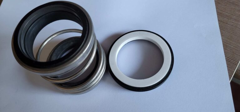
You pull the old seal, slide in the new one, bolt the gland down until it “feels right,” and start the pump. Three weeks later you are back at the same pump pulling the same seal. The difference between a seal that lasts six months and one that lasts three years comes down to compression — and most technicians set it by feel instead of measuring it. A proper compression setting requires exactly three measurements before the pump starts: spring free length, working length, and shaft runout. Skip any one of those, and you are guessing.
Three Measurements Before You Start
A new seal sitting on the bench means nothing until you verify the shaft and the spring can support it. These three pre-checks take ten minutes and prevent the majority of compression-related failures I see in the field.
Check Shaft Runout First
Mount a dial indicator on the stuffing box face and rotate the shaft slowly by hand. Maximum acceptable Total Indicator Reading (TIR) by shaft diameter: 0.05 mm for shafts up to 50 mm, 0.06 mm for 50-75 mm, 0.08 mm for 75-100 mm, and 0.10 mm for shafts over 100 mm. A seal installed on a shaft with excessive runout fails within days to weeks — no amount of perfect compression saves it. If you skip this step, you will be back in a week replacing a seal that never had a chance.
Measure Spring Free Length
Grab your caliper and measure the spring in its uncompressed state. Compare that number to the manufacturer’s specification. A spring that has lost more than 10% of its nominal free length is fatigued and must be replaced, even if it looks fine visually. A fatigued spring generates less closing force per millimeter of compression, which means your “correct” working length still produces under-compression at the seal faces. I have seen technicians reuse springs that measured 12% short — the seal leaked on startup every time.
Confirm Stuffing Box Bore and Depth
Use an inside micrometer or bore gauge accurate to 0.01 mm for the bore diameter, and a depth gauge for the stuffing box depth. You need these numbers for the installation formula in the next section. A steel rule is not accurate enough for the bore — I have watched compression errors start right here with a bad measurement tool.
How to Set Compression on a Component Seal
With a component seal, you are setting the working length, the drive collar position, and the gland gap yourself — one wrong number and the compression is off. The procedure breaks into three sub-steps.
Measure the Working Length
The working length is the installed axial length of the seal head itself (the rotating unit, not counting the seat) when the seal is installed. This single number determines how much the spring is compressed. If the working length is too long, the spring is under-compressed — face contact pressure drops, the fluid film becomes unstable, and the seal leaks. Too short, and you over-compress the spring — the faces overheat from excessive contact pressure, the elastomers distort, and the seal fails prematurely.
Your target: the seal drawing’s specified installed working length, held within +/- 0.5 mm. Use a depth micrometer, not a steel rule, for this measurement. Half a millimeter is the difference between a seal that runs and one that does not.
Position the Drive Collar
With the stationary seat installed, slide the rotating assembly onto the shaft. Set the drive collar (or set screws) at the position that produces the correct working length you just measured. Before you start, make sure you are measuring from the correct reference points — shaft shoulder to gland face, not from an old set-screw mark or a scratch on the sleeve. I cannot count the number of installations I have seen where the technician used the old set-screw mark as the reference, and the reference was wrong. That single habit accounts for more compression errors than any other.
Verify with the Installation Formula
Cross-check your setup with this relationship: stuffing box depth (L2) = seat thickness (L1) + seal working length (L) + clearance (1-2 mm). If L2 does not equal L1 + L + clearance within tolerance, something is off — either the seat is not fully bottomed in the bore, or the drive collar position needs adjustment. This formula connects directly to the compression calculation and catches errors before you bolt the gland down.
How to Set Compression on a Cartridge Seal
Cartridge seals arrive with compression pre-set at the factory, which eliminates the working length measurement entirely. But they introduce their own failure category that component seal installers never face.
The procedure is straightforward: slide the cartridge onto the shaft, bolt the gland to the stuffing box, tighten the drive collar set screws onto the shaft, then remove the setting clips (also called centering tabs or step clips). Those clips held the seal faces at the correct compression during shipping. The most common mistake I see is technicians who bolt everything down and forget to remove the clips — the seal cannot load properly against the faces, and it leaks immediately. The second mistake is over-tightening the gland bolts. Cartridge seals have tighter tolerances than component seals, and excessive bolt torque distorts the gland, cocking the stationary seat.
Tighten gland bolts in a crisscross pattern — for a four-bolt gland, follow a 1-3-2-4 sequence. Snug each bolt to finger-tight first, then bring them to final torque in two passes. A cartridge seal installation also requires laser alignment verification and proper piping slope, because compression is only one piece of a cartridge install that can fail.
Both seal types require verification after installation. The difference is where the measurement happens — component seals require it during assembly, cartridge seals require it after assembly by confirming clip removal and gland bolt uniformity.
Compression Targets by Seal Type
Most seals require a compression distance between 0.100 and 0.150 inches (2.5-3.8 mm), but the percentage of spring travel varies by design.
- Single-spring seals: Compress the spring 50-70% of its free length. These seals have one large coil spring and are more forgiving of slight measurement errors because the spring rate is relatively linear across that range.
- Multi-spring seals: Target approximately 90% of free length. Multiple small springs distribute the load evenly, but they operate in a narrower compression window. Under-compressing a multi-spring seal by even a few tenths of a millimeter produces noticeable face leakage.
- Bellows seals: Follow the manufacturer’s specific compression setting — bellows designs vary too widely for a universal percentage. The welded metal bellows acts as both spring and secondary seal, so compression directly affects bellows stress life.
These percentages are general industry guidelines, not absolute rules. Always check the seal drawing first. When the drawing is unavailable — and it often is on older equipment — these ranges give you a reliable starting point that beats guessing by a wide margin.
3 Compression Setting Mistakes That Send You Back to the Shop
Mistake 1: Referencing Old Set-Screw Marks Instead of the Drawing
The most common mistake I see is technicians who never open the seal drawing. They slide the assembly onto the shaft, find the old set-screw mark, and lock the collar there. The previous installation may have been wrong. The shaft may have been machined. The replacement seal may have different dimensions. Every new installation starts from the drawing, not from what the last technician did.
Mistake 2: Adjusting the Open Impeller After Setting Compression
Open impeller pumps require impeller clearance adjustment, and many technicians do it after installing the seal. That adjustment moves the shaft axially, which changes the working length you just set. On a Goulds 3196 or similar design, an impeller adjustment of 0.5 mm shifts the compression by that same 0.5 mm — enough to push a properly set seal into over-compression. Always adjust the impeller first, then set the seal compression.
Mistake 3: Skipping the Runout Check on “Known Good” Shafts
Oceaneering conducted a reliability study across 40 pumps for a North Sea operator and traced the recurring seal failures to 12 findings, led by varying seal installation methods. A shaft that was “good last time” may not be good now. Bearing wear, coupling misalignment, and thermal cycling all change runout over time. Ten minutes with a dial indicator saves weeks of unplanned downtime.
How to Verify Compression Before Startup
After setting compression — whether on a component or cartridge seal — verify before you start the pump. Rotate the shaft manually through two to three full turns. It should feel smooth with light, even resistance. Any binding, catching, or heavy spots indicates misalignment or over-compression requiring disassembly.
Check gland bolt torque one final time in the crisscross pattern. Uneven bolt load cocks the stationary seat and creates a point-load on the seal faces that no amount of correct compression setting can overcome.
During the first 30 minutes of operation, monitor for visible leakage and face temperature. Standard elastomer seals should stay below 80 degrees Celsius at the seal faces during initial startup. Elevated temperature with no visible leakage points to over-compression — the faces are running too tight, generating friction heat that will eventually destroy the carbon face.
Here is a trick that saves time: mark the gland bolt positions with a paint pen before startup. If you need to come back and troubleshoot, you can immediately see whether the bolts have loosened or the gland has shifted.
Your Pre-Startup Compression Checklist
Every seal installation comes down to three numbers: shaft runout within TIR limits, spring free length within 10% of nominal, and working length within +/- 0.5 mm of the drawing specification. Hit all three, and the seal runs. Miss one, and you are on borrowed time.
The technicians I see repeat-failing on the same pumps are not unskilled — they are skipping the measurement step and relying on what worked last time. Conditions change. Shafts wear. Springs fatigue. The drawing and a depth micrometer take ten minutes. The emergency seal replacement takes a full shift plus the cost of lost production. Start treating the seal drawing like a work permit — nothing gets installed until you have read it and measured against it.