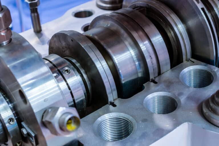
A split mechanical seal is a two-piece seal type — the seal itself is split into halves so it can be wrapped around a shaft without removing bearings or impellers, which is why it shows up on large vertical pumps, in-service pumps, and agitators with overhead drives. Installation of a standard one-piece seal on a horizontal split-case pump follows a different procedure, even though both terms contain “split”; the two should not be confused.
I have installed hundreds of split mechanical seals over the past decade, and the ones that leak almost never fail because of the seal itself. They fail because someone skipped a measurement, contaminated a face, or cranked the gland bolts too tight. Yet the standard advice is “follow the manufacturer’s instructions” and “tighten evenly” — not a single torque value or tolerance in sight.
Split seals have more leak paths than a cartridge seal by design. Two-piece faces, split O-rings, a bolted gland — each joint is a potential leak if your preparation is off. Roughly one in four split seal failures traces back to poor installation, not seal defects. Below are the actual numbers, tolerances, and field-tested checks I use on every job.
Before You Touch the Seal
A split seal installation starts 30 minutes before the seal comes out of the box. The most common mistake I see is technicians jumping straight to assembly on a shaft that should not have a new seal on it yet.
Tool Checklist
Gather everything before you start. Walking back to the shop mid-installation with lubricant on your gloves is how seal faces get contaminated.
- Dial indicator with magnetic base (for shaft runout)
- Inside micrometer or bore gauge (seal chamber bore)
- Outside micrometer (shaft diameter under seal)
- Torque wrench (inch-pound or foot-pound range depending on gland bolt size)
- Feeler gauge set (for checking gap uniformity)
- Clean lint-free rags (not shop towels — fibers embed in seal faces)
- Manufacturer-approved O-ring lubricant (not petroleum jelly, not silicone)
Shaft and Bore Inspection
Check shaft runout before anything else. Mount the dial indicator on the seal chamber face and rotate the shaft by hand. Maximum acceptable runout is 0.002 inch TIR (Total Indicator Reading) for standard ball or roller bearing pumps. If you exceed that, stop. Installing a new seal on a shaft with excessive runout guarantees you will be back in a week pulling the same seal.
Measure shaft diameter at the seal contact area with an outside micrometer. Compare to the seal drawing. A worn shaft undersized by more than 0.002 inch will not hold the rotating element in position.
Inspect the shaft surface under the seal. The finish must be mirror-smooth — 32 microinch Ra or better. Scratches, nicks, or grooves running lengthwise will seep and start a leak that no amount of tightening fixes. If the shaft is scored, sleeve it or repair it before proceeding.
Check the seal chamber bore for corrosion, pitting, or buildup. Clean it to bare metal and measure the bore diameter — the stationary seat must slide in without force, and corrosion deposits change the effective bore size.
One more check that gets skipped too often: bearings. Heinz Bloch’s analysis of 11,000 seal failures across 148 plant sites found that 13% traced directly to bearing condition. Grab the shaft and try to move it axially and radially. Any perceptible play means the bearings need attention first.
If you just removed the old seal, examine it. Uneven carbon face wear tells you misalignment is present and needs correcting before the new seal goes on.
Assembling the Seal Halves
Split mechanical seals come apart into a rotating assembly and a stationary assembly, each split into two halves at the parting line. The order matters: rotating half goes on first.
Rotating Half Installation
Unwrap the seal faces last. Keep protective covers on until the moment of installation. Even fingerprint oils on a lapped carbon face create a contamination film that prevents the faces from seating during break-in.
Handle seal faces by the outer edges only. If you drop a face half — even onto a clean rag — inspect it under angled light. A scratch invisible at normal viewing shows up as a bright line.
Position the two rotating halves around the shaft and mate them at the split line. The O-ring at the split must seat fully in its groove without twisting or pinching. Apply a thin film of manufacturer-approved lubricant to the O-ring only — never to the seal face. Never use silicone, PTFE tape, or petroleum-based lubricants. These swell elastomers and contaminate the face.
Set the drive collar into position and check the setting dimension — the distance from a reference surface to the seal face. The manufacturer’s drawing specifies this to within 1/32 inch typically. Too much compression accelerates wear; too little lets the faces separate under pressure.
Snug the set screws on the drive collar in a star pattern, not sequentially around the circumference. Verify the shaft still rotates freely. Binding means the rotating element is misaligned.
Stationary Half Installation
The stationary half seats into the seal chamber bore or gland plate. This is where most technicians run into trouble.
Dry-fit the stationary halves into the bore without the O-ring first. They should slide in with light hand pressure. If you need to hammer or force them, the bore is undersized from corrosion buildup or the seal is the wrong size. Forcing a stationary seat distorts the ring and guarantees a leak at the split line.
Once the dry fit checks out, install the O-ring, lubricate lightly, and press the two stationary halves into the bore evenly. The O-ring must compress uniformly around the full circumference.
Align the split lines of the stationary halves 90 degrees offset from the rotating half split lines. This prevents a continuous leak path across both sets of splits.
Gland Plate and Final Tightening
More split seals get destroyed at this step than any other, because the natural instinct when something leaks is to tighten harder.
Position the Gland and Verify Squareness
Position the gland plate and start all bolts by hand. Verify the gland sits square to the stuffing box face — a cocked gland creates uneven face loading that no torque sequence can fix.
Tighten in a Star Pattern, Three Passes
Tighten the gland bolts in a star pattern, not in a circle. As a reference baseline, marine mechanical seal applications specify approximately 6 ft-lbs for shaft sizes 3/4 to 1-3/8 inch and 8 ft-lbs for shaft sizes 1-1/2 to 3-3/4 inch. Your specific seal’s installation drawing will have the exact value — always check it. But these numbers illustrate the point: gland bolt torque is low. Much lower than most technicians expect.
Tighten in three passes:
- First pass: finger-tight plus a quarter turn.
- Second pass: 50% of final torque.
- Third pass: full specified torque. After the final pass, recheck the first bolt — gland gasket compression redistributes load during the sequence.
Why Over-Tightening Destroys Split Seals
Over-tightening distorts the gland plate. A distorted gland cocks the stationary face relative to the rotating face, creating a taper across the sealing surface. The seal leaks. The technician tightens more. The distortion worsens. This cycle destroys seals. If a seal leaks after proper torque, the problem is face condition, alignment, or compression setting — not bolt tightness.
After tightening, spin the shaft by hand through several full rotations. It should turn with light, even drag. Heavy drag or binding means the faces are overloaded or misaligned. Back off the gland bolts and recheck.
Installation Mistakes That Cause Immediate Leaks
One in four split seal installations fails prematurely. After years of doing these jobs — and fixing other people’s work — three mistakes account for the majority:
- Contaminated seal faces. The number-one killer. Touching the lapped face with a bare finger leaves enough oil to prevent proper seating. Setting the face on a workbench picks up grit you cannot see. I have pulled seals at two weeks that showed a single radial scratch across the carbon — one piece of embedded grit from an unclean assembly. Keep faces wrapped until the last possible moment. If you contaminate a face, clean with isopropyl alcohol on a lint-free wipe and inspect under angled light before reinstalling.
- Skipping the shaft runout check. Split seals tolerate less shaft deflection than cartridge seals because the split parting lines add compliance challenges. A shaft running at 0.004 inch TIR may work with a one-piece cartridge seal for years, but a split seal on the same shaft will weep at the parting line within weeks. The five minutes with a dial indicator saves eight hours of teardown later.
- Over-tightening gland bolts. The technician finishes the install, starts the pump, sees a drip, and reaches for the wrench. Within three additional quarter-turns, the gland is distorted beyond recovery. The correct response to a post-startup drip is to wait. Many split seals weep slightly during the first few minutes as the faces seat. If leakage persists after 15 to 30 minutes, shut down and investigate face condition and alignment — not bolt tightness.

Startup and Post-Installation Monitoring
Initial Startup Procedure
Before you hit the start button, verify the seal flush system is connected and flowing. Confirm liquid reaches the seal chamber. Starting a seal dry — even for seconds — can score the faces permanently.
Vent the seal chamber if the pump orientation allows air to collect there. Trapped air means no lubrication film on the faces at startup.
Start the pump and watch the seal area immediately. A light moisture film on the gland face is normal during the first few minutes — the faces are bedding in. Heavy dripping or a steady stream means something is wrong. Shut down and diagnose.
What Normal Break-In Looks Like
A properly installed split seal shows a thin moisture film at startup that diminishes over 15 to 30 minutes. After break-in, the seal runs essentially dry at the gland face. A trace of dampness is acceptable. Visible dripping is not.
Three failure timing patterns tell you what went wrong. Immediate leaks at startup indicate face problems — contamination, scratches, or faces not seating flat. Gradual leaks developing over days or weeks point to alignment issues or bearings letting the shaft walk. Leaks appearing only at shutdown suggest the pump is operating off its best efficiency point.
If a cartridge seal installation leaks, you pull the whole cartridge for bench inspection. With a split seal, you can often diagnose in place by checking face contact patterns and O-ring condition without full disassembly — that is the real maintenance advantage of the split design.
Monitor weekly for the first month, then roll into your standard pump schedule. A split seal installed correctly on a pump with good bearings and alignment lasts as long as a one-piece seal in the same service.
Installation Checklist
The seal itself is rarely what fails — it is the 30 minutes of preparation that determines whether you get two years of service or two weeks. Every split seal job I walk away from confidently has the same five checks in common: shaft runout under 0.002 inch TIR, clean mirror-finish shaft surface, faces uncontaminated, setting dimension verified, and gland bolts torqued in a star pattern to spec.
- Shaft runout measured and under 0.002 inch TIR
- Shaft surface smooth, no axial scratches under seal contact area
- Seal chamber bore clean, measured, and within spec
- Bearings checked for axial and radial play
- Seal faces handled by edges only, inspected under angled light
- O-rings lubricated with approved lubricant only
- Rotating half split line offset 90 degrees from stationary half
- Setting dimension matched to manufacturer drawing
- Gland bolts torqued in star pattern, three passes
- Shaft rotates freely with light, even drag after tightening
- Flush line connected and flowing before startup
The first hour after startup tells you everything. If the seal is dry at the gland face after 30 minutes of running, you did the job right.