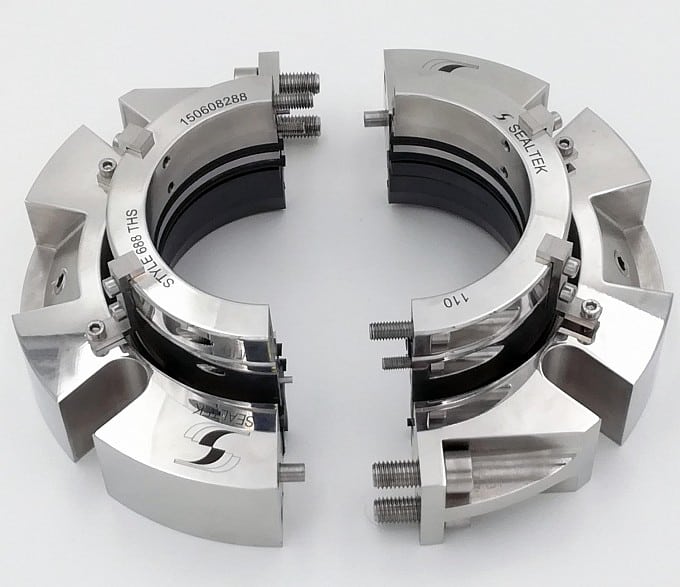
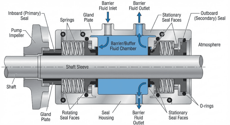
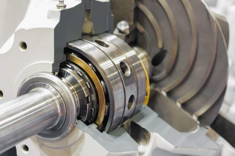
Roughly 70% of pumps pulled from service for maintenance come out because the mechanical seal failed. I’ve tracked the root causes on hundreds of those jobs, and inadequate cooling is behind more of them than most teams realize. The frustrating part is not that cooling technology is lacking — it is that the right information is scattered across API plan catalogs, cooler product pages, and valve marketing brochures, with no single source connecting the dots between your pump’s conditions and the right cooling approach.
When Does a Mechanical Seal Need Cooling?
A seal cooling system is the combination of flush, barrier fluid, and heat-removal hardware that keeps the mechanical seal below its material and fluid-phase limits. Not every hot seal needs a cooling system.
Modern seal designs handle continuous operation above 700 deg F in clean, steady-temperature services. The trigger is not a specific temperature — it is what the temperature does to the seal environment.
Temperature cycling kills seals faster than steady high heat. When a pump cycles between operating temperature and ambient, process fluid can solidify into tar-like deposits with viscosities above 1,000 cP. Those deposits jam seal faces open.
I have pulled seals at three months that should have lasted three years, and every time the problem was cycling — not peak temperature.
Three conditions reliably demand dedicated cooling:
- Process fluid temperature exceeds the elastomer or face material limit. Above 400 deg F, metal bellows seals replace pusher designs — but the fluid still needs thermal management.
- The pumped fluid is near its boiling point, where even moderate seal face heat generation can cause vaporization between the faces.
- Dissolved solids or polymers crystallize on faces as temperature rises, creating abrasive particles in the seal chamber.
Before you start designing a cooling circuit, verify the actual seal chamber temperature — not the process temperature at the pump nozzle.
Cooling Methods for Single Seals
Single seal cooling breaks into two categories: flush plans and external cooling hardware. Thermosiphon systems, also covered below, serve dual seals.
Flush Plans
Plan 11 takes fluid from pump discharge, routes it through the seal chamber, and returns it to the process past the throat bushing. Simple piping, no external utilities, but the flush fluid is at process temperature. Plan 11 works for clean, moderate-temperature services where lubrication matters more than heat removal.
Plan 21 adds a heat exchanger between pump discharge and the seal chamber. The flush fluid arrives cooled, giving real temperature reduction at the faces. This plan typically covers services between 200 deg F and 350 deg F.
Plan 23 recirculates seal chamber fluid through a heat exchanger and back. Because it re-cools the same fluid rather than using fresh coolant each pass, Plan 23 cuts cooling water demand by over 90% compared to single-pass plans. For any application where cooling water cost matters, Plan 23 should be the default consideration.
Thermosiphon Systems (Dual Seals)
In dual seals, a thermosiphon uses natural convection — hot fluid rises, cooled fluid descends — to circulate buffer fluid through a reservoir and heat exchanger without a pump. No moving parts, no external power, minimal maintenance.
The limitation is heat capacity. Thermosiphon flow depends on the temperature differential driving convection, so high-heat applications overwhelm it. For moderate heat loads, a properly piped thermosiphon provides reliable, hands-off cooling. When heat generation exceeds what natural convection handles, you move to Plan 54 with an external circulation pump.
The most common mistake I see on thermosiphon installations is improper tubing slope. A half inch per foot of rise is the minimum. Skip that, and vapor locks kill circulation entirely.
External Cooling Hardware
Cooling jackets and standalone coolers remove heat from outside the seal chamber. Natural air coolers handle up to roughly 2,300 watts, forced air units reach 9 kW, and liquid-cooled exchangers push to 18 kW for the heaviest thermal loads. Match cooler capacity to your calculated heat load with margin — undersizing is a common and expensive mistake.
Cooling Methods for Dual Seals
Dual seal cooling adds a challenge single seals avoid: the barrier or buffer fluid between the face pairs must stay within a tight temperature and viscosity window, or both seal sets degrade together.
Plan 52 uses an unpressurized reservoir with a pumping ring driven by shaft rotation. Because circulation depends on shaft speed, Plan 52 performance drops at low RPM and falls back to thermosyphon flow alone when the shaft is stationary. For constant-speed pumps in non-hazardous service, it is simple and effective.
Plan 53A pressurizes the barrier fluid reservoir with external gas, maintaining pressure 20 to 25 psig above process pressure. An integral cooling coil manages temperature. Unlike Plan 52, Plan 53A holds its barrier pressure independently of shaft speed, though its circulation still relies on the pumping ring, making it the better choice for any service requiring a pressure barrier at zero RPM.
For the highest-demand applications, Plan 54 uses an external pumping system to circulate barrier fluid through a dedicated heat exchanger. The added hardware means more potential failure points, but Plan 54 earns its place on high-temperature services where no passive system can handle the load.
What API Plan Numbers Don’t Tell You About Real-World Cooling
API 682 describes what each plan does — not how to select one for your specific pump. Two gaps catch engineers repeatedly.
Over-Flushing Wastes More Than Water
The conventional recommendation is roughly 1 gpm flush flow per inch of seal size. Thermodynamic calculations for specific seal configurations show that 0.32 gpm is sufficient for many applications — meaning engineers may be over-flushing by three times what the seal actually needs.
Excessive flush flow can cool the seal chamber below the point where process fluid maintains proper viscosity for face lubrication. In some services, rapid coolant flow through the jacket raises heat transfer and pushes the chamber further into that overcooled range. More coolant does not always mean better cooling. Validate flush flow against the actual heat load for your seal size, speed, and fluid properties before defaulting to the API baseline.
Venting and Installation Faults Masking as Cooling Failure
At East Kentucky Power Cooperative, three cooling water pumps experienced persistent seal failures that looked like cooling problems — elevated temperatures, premature face wear, shortened seal life. Diagnostics by Lev Nelik’s team using multi-point pressure, temperature, vibration, and flow monitoring revealed a different root cause.
The pumps were operating close to their Best Efficiency Point (BEP); the upper seals ran dry for lack of venting and the lower seals stuck to the shaft on swollen elastomer. The apparent thermal failure was actually a venting and installation problem.
If you skip this step — checking that the seal chamber is vented and the seal was installed with the right lubricant — you will be back in a week replacing the same seal. Rule those out before blaming the cooling system.
Common Cooling System Mistakes
Five setup errors account for most cooling system underperformance, and every one is preventable.
- Mineral buildup in cooling jackets. Scale insulates the heat transfer surface. A jacket can lose half its capacity within a year if water quality goes unmanaged.
- Coolant flowing too fast. Higher velocity actually raises heat transfer, so excess flow mainly costs water, not cooling capacity. If you are running maximum flow and still seeing high temperatures, look for scale or trapped air instead.
- Trapped air in the circuit. Air pockets create dead zones with zero heat transfer. Vent completely at startup and after any maintenance that opens the circuit.
- Thermal bushing in the wrong position. The bushing belongs at the bottom of the stuffing box. Install it at the top and you get a stagnant hot zone exactly where you need cooling most.
- Flat tubing on thermosiphon runs. Natural convection needs gravity. Maintain a minimum half inch per foot slope — flat or sagging runs create vapor traps that stop circulation.
Choosing the Right Cooling System
Start with three questions: What is the actual seal chamber temperature under operating conditions? Is the process fluid clean or does it deposit on hot surfaces? Does the seal arrangement need a pressurized barrier?
Single seals in moderate-temperature clean service typically need nothing beyond Plan 21 or Plan 23. Dual seals in hazardous or high-temperature service point toward Plan 53A or Plan 54. Thermosiphon fits the middle ground where passive cooling handles the heat load without external utilities.
The decision most engineers skip is measuring the real thermal load before picking a plan. Every application has different shaft speed, fluid properties, and ambient conditions. Match the system to the actual demand — not to habit or to the last pump you worked on — and the seal will run for years instead of months.
Start With PV, Not the Catalog
The mistake that drives most over- and under-specified cooling systems is selecting a plan from the catalog before calculating the actual heat load. Two field tests grounded in PV (pressure × velocity at the face) tell you whether cooling is even needed before you escalate to Plan 23 / 53A / 54.
Delta-T field check. Measure inlet and outlet temperature on the seal chamber (or the flush line if Plan 11 is already running). A ΔT under 10–15°F on stable flow means the heat the seal generates is being carried away by the existing internal flush — additional cooling is not the lever. A ΔT above 30°F with low flow means cooling is the lever, but so is increasing flush flow before adding hardware. Run the ΔT check before specifying a Plan 23 cooler.
PV decision. Calculate PV = sealed pressure × face mean velocity. Below the seal manufacturer’s published PV limit (typically 0.5–3 MM psi·fpm depending on face material pairing) with margin, internal cooling from the process fluid suffices. Approaching the PV limit means the faces are operating in the heat-management regime where external cooling actively prevents face damage. Most “does this need cooling” questions answer themselves once PV is computed against the face material pairing.
Thermosyphon vs Forced Circulation in Dual Seals
For dual seals specifically, the cooling circuit choice is not which plan to specify but how the barrier or buffer fluid circulates. Thermosyphon relies on natural convection — heat at the seal lowers buffer-fluid density at the source, gravity drives the cool return down from the reservoir. Works passively, requires no utilities, but demands strict piping discipline (½ inch per foot slope minimum, no flat runs, no horizontal traps — see Common Mistakes above). Forced circulation uses an integral pumping ring on the seal to drive the buffer fluid. Higher heat rejection capacity, less sensitive to piping geometry, but adds a moving part inside the seal cavity (Plans 52, 53A, 53B and 53C all circulate this way). When the seal chamber sees high heat loads, forced circulation is the right call; at standstill, only thermosyphon keeps the fluid moving. When heat loads are moderate and the pump runs continuously, thermosyphon is simpler and more reliable.