The chemical degradation rate of barrier fluid doubles for every 18 F (10 C) rise in temperature. A fluid that lasts six months at 130 F needs changing every three months at 148 F. That single relationship explains why the cooling system — not the seal itself — determines how long a double mechanical seal installation actually lasts.
Most double seal guidance focuses on pressure differentials: maintain 15-30 psi above process pressure, monitor the accumulator, check the nitrogen blanket. But I’ve pulled more failed seals caused by overheating than by pressure loss. Temperature management is co-equal with pressure management, and ignoring it is the fastest way to shorten seal life.
Why Double Seals Need Dedicated Cooling
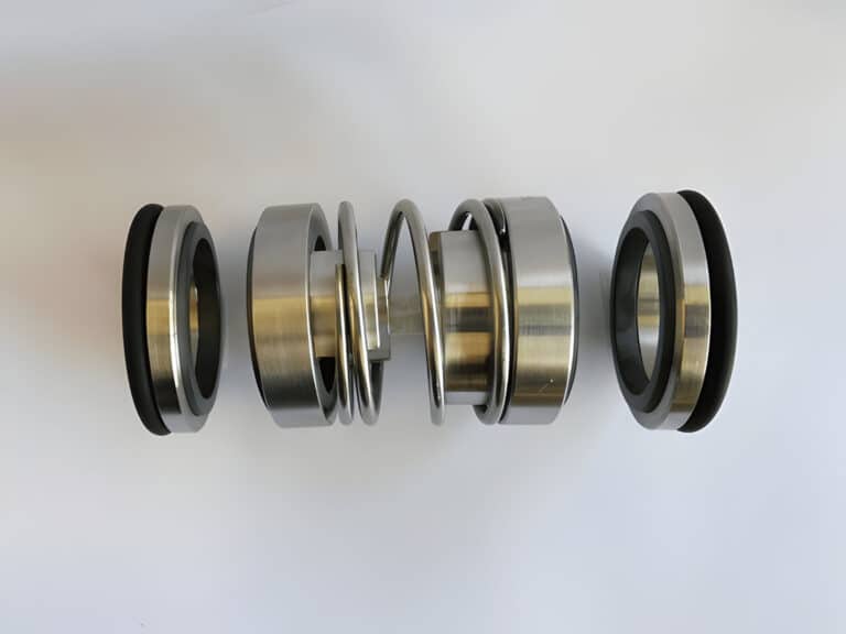
Two sets of seal faces generating friction heat into a closed barrier fluid volume — that is the fundamental challenge. Without a dedicated cooling circuit, fluid temperature climbs until the faces blister, score, or run dry from vapor formation. Carbon faces develop radial cracks. Elastomers harden. The barrier fluid breaks down, losing both lubrication and heat-transfer capacity.
Process fluid cooling alone is rarely sufficient because the barrier fluid circuit is isolated from the process. A closed-loop system like API Plan 23 can cut cooling water demand by over 90% compared to once-through designs, making dedicated cooling both more effective and more economical.
Cooling Circuit Components
A double seal cooling system has three functional groups: the fluid loop, the heat exchanger, and the instrumentation.
The Barrier Fluid Loop
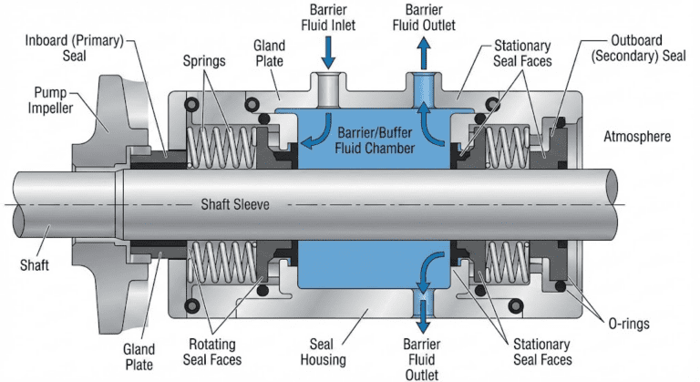
The loop circulates barrier or buffer fluid between the seal chamber and an external reservoir. Fluid absorbs heat at the seal faces, travels through piping to the heat exchanger, sheds heat, and returns cooled.
Piping layout makes or breaks this circuit. I worked on a Goulds 3196 ammonia pump at a cold storage facility where the seal failed within one year. The root cause was piping sloped in the wrong direction with tight 90-degree elbows instead of gentle slopes. The seal was fine. The cooling path was not. Slopes must direct flow consistently — warm fluid rising, cooled fluid falling — with sweeping bends rather than sharp turns.
Heat Exchangers
Shell-and-tube or plate-type exchangers reject heat from barrier fluid to plant cooling water. Size the exchanger for actual heat load at the seal faces, not nameplate flow rate. Undersized exchangers let barrier fluid temperature creep up over weeks until degradation accelerates silently.
Instrumentation
Temperature gauges on barrier fluid supply and return lines are the minimum. The differential tells you how much heat the faces are generating — a rising differential means increasing friction, an early warning before visible damage.
API 682 specifies allowable temperature rise limits: 15 F (8 C) for water-based fluids and 30 F (16 C) for mineral or synthetic oil systems. Exceed these and the cooling system is either undersized or compromised.
Thermosyphon vs Forced Circulation
How Thermosyphon Works
A thermosyphon system drives barrier fluid circulation using natural convection — no pump, no external power. Warm fluid near the seal faces becomes less dense and rises to a reservoir above the seal. The reservoir or an integrated heat exchanger cools the fluid, increasing density so it flows back down by gravity.
The physical constraints are hard limits: the reservoir must sit approximately 1-2 m above the seal and no more than 2 m to either side. Exceed these distances and natural convection stalls.
A thermosyphon also doubles as a contamination barrier and predictive maintenance tool. The cooling medium never contacts the process directly, and fluid level or temperature changes in the reservoir signal seal degradation before catastrophic failure.
When to Use Forced Circulation
Forced circulation adds a small pump to drive barrier fluid through the circuit. It becomes necessary when heat loads exceed thermosyphon capacity, piping runs exceed the 2 m horizontal limit, or the reservoir cannot be positioned above the seal.
I recommend forced circulation only when physical layout prevents proper thermosyphon positioning or process temperature consistently pushes barrier fluid above API 682 limits. The added pump introduces its own maintenance burden, so the complexity must be justified thermally.
API Flush Plans for Cooling
Each API flush plan has fundamentally different heat removal capabilities. Selecting a plan based only on pressure requirements ignores the thermal side entirely.
| Plan | Cooling Method | Heat Removal | Best Application |
|---|---|---|---|
| Plan 23 | Closed-loop with cooler | High | Hot process fluids, temperature-sensitive seals |
| Plan 32 | External clean fluid injection | Moderate | Dirty or abrasive processes |
| Plan 52 | Unpressurized buffer reservoir | Low-moderate | Tandem seals, leakage detection |
| Plan 53A | Pressurized barrier (nitrogen) | Moderate | Hazardous fluids, zero-leakage |
| Plan 54 | External pressurized supply | High | Critical hazardous service |
Plan 53A is the most common choice for hazardous service, but barrier pressure is usually capped at 100 psi, and fluid must maintain at least 10 psi above seal chamber pressure. When the thermal load is high and the reservoir is small, fluid heats up faster than thermosyphon can reject it.
The choice between 53A and 54 often comes down to whether thermosyphon can keep barrier fluid within API 682 temperature limits. Plan 54 solves the heat problem through continuous fresh fluid but adds significant system complexity.
What API Plan Specs Don’t Tell You About Heat Management
The degradation doubling rule means a system running just 20 degrees above design temperature consumes barrier fluid at twice the planned rate. By the time someone notices the fluid looks dark and smells burnt, the seal faces have been running on degraded lubricant for weeks.
Viscosity selection is another gap the specs don’t address. Synthetic barrier fluids in the ISO Grade 5 to 20 range work well, but oils at Grade 32 or higher cause carbon seal face blistering. I’ve seen this failure pattern dozens of times — a site switches to a higher-viscosity oil thinking it improves lubrication, and the carbon faces develop subsurface blisters within months because heavier fluid traps heat in the face pores.
The API 682 standard specifies allowable temperature rise for a reason. But piping layout, exchanger fouling, and air pockets can push you past those limits without triggering any pressure alarm. The cooling circuit can appear fully functional — pressurized, circulating, no leaks — while the fluid quietly degrades.
Signs Your Cooling System Is Failing
Rising barrier fluid return temperature is the earliest indicator. If the supply-return differential increases over weeks, the seal faces are generating more friction heat from wear, misalignment, or contamination.
Darkened barrier fluid means thermal degradation has already started. Pull a sample and compare to fresh fluid — shifted color or acidic smell confirms the cooling system has been undersized or compromised.
Air entrapment defeats cooling even when pressure looks normal. At Spurlock Station, East Kentucky Power Cooperative’s cooling water pump experienced repeated seal failures despite adequate system pressure. Seal faces showed a phonographic finish with edge chipping — classic dry running. The cause: missing air vent ports allowed trapped air to prevent barrier fluid from reaching the upper seal faces. Installing proper vent piping resolved the recurring failures.
Track reservoir makeup rates. A sudden increase without visible external leakage means barrier fluid is migrating past worn seal faces into the process side — and cooling system temperature data often explains why.
The Bottom Line
A pair of temperature gauges on barrier fluid supply and return lines costs almost nothing compared to the information it provides: whether the cooling circuit is removing heat as designed, whether seal faces are wearing abnormally, and whether barrier fluid will last to the next scheduled change.
Most double seal installations I review have adequate pressure systems and inadequate temperature visibility. Track the differential over time, and the thermosyphon reservoir becomes a diagnostic window — rising baseline temperature signals exchanger fouling, falling fluid level signals face wear, and both trends give you weeks of lead time before the seal fails.