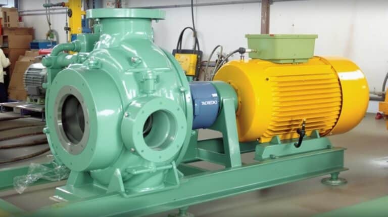
Seal Chamber Pressure Calculator
Calculation Formula:
Example Calculation:
A pump with 20 PSI suction pressure, pumping water (SG=1.0) with 10 feet of head differential: 20 + (1.0 × 10 × 0.433) = 24.33 PSI seal chamber pressure.
Seal chamber pressure calculation determines the exact pressure acting on your mechanical seal faces—critical for preventing premature seal failure and costly pump downtime. The basic formula is: Seal Chamber Pressure = Suction Pressure + (Specific Gravity × Head Differential × 0.433).
Getting this calculation right means the difference between a seal lasting years versus failing in weeks. For maintenance teams managing centrifugal pumps, understanding this pressure directly impacts your MRO budget and equipment reliability.
Seal Chamber Pressure Basics
Seal chamber pressure is the actual pressure inside the stuffing box where your mechanical seal operates. This pressure directly affects seal face loading, heat generation, and ultimately, seal life.
Every mechanical seal has an optimal pressure range. Exceed it, and you’ll see rapid face wear or catastrophic failure. Run too low, and you risk inadequate lubrication or vapor formation.
The pressure in your seal chamber isn’t the same as discharge pressure. It runs at or slightly above suction pressure on pumps with back wear rings and balance holes, and can approach discharge pressure without them, though this varies with impeller design and wear ring clearances.
The Core Calculation Formula
The seal chamber pressure formula for standard centrifugal pumps follows this equation:
P(seal) = P(suction) + (SG × H × 0.433)
Where:
- P(seal) = Seal chamber pressure (PSI)
- P(suction) = Suction pressure (PSI)
- SG = Specific gravity of pumped fluid
- H = Head differential between suction and seal chamber (feet)
- 0.433 = Conversion factor (PSI per foot of water)
This seal chamber pressure formula assumes standard pump configurations without special flush arrangements.
Step-by-Step Calculation Process
Start by measuring your suction pressure at the pump inlet using a calibrated gauge. Record this value in PSI.
Next, determine the specific gravity of your pumped fluid. Water equals 1.0, while chemicals vary—sulfuric acid might be 1.84, and gasoline around 0.74.
Calculate the head differential the impeller adds between suction and the seal chamber. With balance holes, this is often negligible. Without back wear rings or balance holes, it can approach the full pump head.
Multiply your specific gravity by the head differential, then by 0.433. Add this result to your suction pressure.
For example: A pump with 20 PSI suction pressure, pumping water (SG=1.0) with 10 feet of head differential:
20 + (1.0 × 10 × 0.433) = 24.33 PSI seal chamber pressure.
Seal Chamber Pressure vs Seal Pot Pressure (Don’t Confuse Them)
Seal chamber pressure and seal pot pressure sound similar but describe two completely different things, and the calculation approach is not interchangeable.
Seal chamber pressure is the pressure inside the stuffing box where the mechanical seal faces actually run. It is a consequence of pump hydraulics—suction pressure plus the head contribution from impeller geometry, as calculated by the formula above. You measure it indirectly from suction and head data; you do not set it manually.
Seal pot pressure is the pressure of the barrier or buffer fluid held in an external reservoir on a dual seal arrangement. It is not derived from pump suction at all.
On an API Plan 52 unpressurized buffer system, the seal pot sits near atmospheric with only a slight blanket. On a pressurized Plan 53A barrier system, the pot is pressurized with inert gas to roughly 20-40 PSI above seal chamber pressure, and that setpoint comes from the operator, not from a fluid-column equation.
For dual seal systems, reservoir pressure is set at the operator panel and maintained against leakage—separate from, but referenced to, the pump-side hydraulics calculated here. The what is a seal pot overview covers that sizing logic in full.
FAQs
What’s the typical seal chamber pressure in a standard centrifugal pump?
For single-stage centrifugal pumps with back wear rings and balance holes, seal chamber pressure runs at or slightly above suction pressure. Without balance holes or back rings, it can approach discharge pressure. Actual pressure varies with pump design and operating conditions.
How do balance holes affect seal chamber pressure calculation?
Balance holes dramatically reduce seal chamber pressure to nearly suction pressure levels. They allow high-pressure fluid behind the impeller to recirculate to suction, eliminating most pressure buildup. Include this reduction when calculating pressure for pumps with balance holes.
Should I use gauge pressure or absolute pressure in calculations?
Use gauge pressure (PSIG) for standard seal chamber pressure calculation unless specifically working with vapor pressure margins or NPSH calculations. Most seal manufacturers rate their products in gauge pressure, making this the practical choice for maintenance applications.
How often should seal chamber pressure be recalculated?
Recalculate whenever pump conditions change significantly—new fluid service, speed changes, or system modifications. Also recalculate when wear ring clearances exceed manufacturer tolerances, typically during major overhauls every 3-5 years depending on service severity.
What safety factor should I apply to calculated seal chamber pressure?
Apply a 1.5x safety factor for critical services or when calculation uncertainty exists. For standard water services with known conditions, a 1.25x factor suffices. This ensures your selected seal handles pressure spikes and calculation variations without failure.