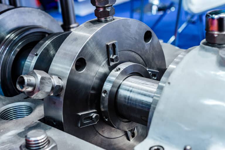
The 4th edition of API 682 quietly flipped the default instrumentation on seal pot systems from switches to transmitters. If you specified a system last year without explicitly requesting switches, you may have already received transmitters — and a cost surprise. That single change captures why seal pot requirements under API 682 deserve dedicated attention, not a footnote buried in a 260-page standard. Seal-pot sizing depends on which of the API piping plans you specify.
Reservoir Sizing Requirements
A 3-gallon reservoir for shafts under 2.5 inches and a 5-gallon reservoir for larger shafts — those are the defaults most engineers memorize. But treating those numbers as design answers rather than starting points is where compliance problems begin.
Default Volumes by Shaft Size
The API 682 defaults serve as minimum baselines:
- Shaft diameter below 2.5 inches: 3-gallon (11.4 L) reservoir
- Shaft diameter 2.5 inches and above: 5-gallon (18.9 L) reservoir
- Plan 53B: 5-gallon bladder with 9-gallon accumulator
These defaults assume moderate seal leakage rates and ambient conditions within normal refinery ranges. They do not account for high-temperature services that accelerate fluid degradation, high-leakage applications where fluid consumption exceeds typical rates, or remote installations where refilling access is limited.
The 28-Day Refilling Interval
The real sizing constraint is not the gallon default — it is the requirement for sufficient working volume for at least 28 days of operation without refilling. This interval drives actual reservoir sizing more than shaft diameter does.
I’ve reviewed systems where the 5-gallon default technically met the shaft-size criterion, but the combination of elevated seal chamber temperature and above-average leakage meant the reservoir needed topping off every two weeks. That system was non-compliant from day one.
Calculate your expected fluid consumption rate first. Factor in both normal leakage and thermal expansion losses. If the math shows your default reservoir empties before 28 days, you need a larger vessel — regardless of what the shaft-size table says.
Pressure and Fluid Requirements by Plan Type
Pressure, temperature, and viscosity requirements split sharply between buffer and barrier configurations. Getting this wrong doesn’t just affect compliance — it affects seal life.
Plan 52: Buffer System
Plan 52 operates unpressurized with buffer fluid maintained below seal chamber pressure and below 0.28 MPa (40 psi). The reservoir sits at atmospheric pressure with a vent to atmosphere, relying on thermosyphon circulation for cooling.
Buffer fluid temperature rise limits are strict: maximum 15 F rise for water-based fluids and diesel, 30 F for mineral and synthetic oils. Maximum bulk fluid temperature should not exceed 150 F. When the process fluid is hot enough to push buffer fluid temperatures beyond these limits, you need a cooler in the thermosyphon loop or a different plan altogether.
Plan 53A: Pressurized Barrier
Plan 53A maintains barrier fluid pressure 20-25 psig (1.4-1.73 bar) above maximum process pressure at the seal chamber. This positive pressure differential is what keeps process fluid from crossing the inboard seal faces — and it is the single most critical parameter to maintain.
The same fluid property limits apply: 15 F rise for water-based solutions, 30 F for oils, 150 F maximum bulk temperature. Fluid viscosity at minimum operating temperature must stay below 500 cSt, with startup viscosity below 68 cSt. These viscosity limits exist because thick fluid kills thermosyphon flow, and dead circulation kills seals.
Fluid replacement intervals are capped at six months regardless of fluid condition. I’ve seen operators stretch this to a year because the fluid “looked fine.” Barrier fluid degradation is not always visible — oxidation products accumulate below detection thresholds until they damage seal faces.
Plan 53B: Bladder Accumulator
Plan 53B is the most engineering-intensive configuration. The 4th edition expanded Annex F from 7 to 42 pages dedicated to Plan 53B tutorial calculations — a 6x increase that reflects chronic field sizing problems the earlier edition didn’t adequately address.
The default configuration specifies a 5-gallon bladder with a 9-gallon accumulator. But thermal variations in ambient temperature directly affect bladder precharge pressure and available fluid volume. A system sized for Gulf Coast summers may not maintain adequate pressure during a Minnesota winter shutdown.
One petrochemical complex in China deployed Plan 53B across 670 pumps — the largest known single-site implementation. That scale of deployment required custom thermal calculations for every pump location, not a blanket application of defaults. The engineering effort behind Plan 53B is proportional to its Annex F page count.
| Requirement | Plan 52 | Plan 53A | Plan 53B |
|---|---|---|---|
| Pressure | < 40 psi, below chamber | 20-25 psi above process | Bladder precharge + barrier |
| Default volume | 3 or 5 gal | 3 or 5 gal | 5-gal bladder / 9-gal accumulator |
| Temp rise limit | 15 F (water) / 30 F (oil) | 15 F (water) / 30 F (oil) | 15 F (water) / 30 F (oil) |
| Max bulk temp | 150 F | 150 F | 150 F |
| Refill interval | 28 days min | 28 days min | Accumulator compensates |
Piping Configuration and Thermosyphon Requirements
Thermosyphon circulation depends entirely on piping geometry. Natural convection is unforgiving — a single incorrect slope or connection point stops flow completely.
The minimum piping slope from seal to reservoir is 1:10. That means 1 unit of vertical rise for every 10 units of horizontal run. Anything less, and the density differential between hot and cool fluid cannot sustain circulation. I’ve pulled seals that failed within weeks of a commissioning where the piping crew ran a “close enough” slope at roughly 1:15. There is no close enough with thermosyphon flow.
All connections should use stainless-steel tubing rather than carbon steel pipe. Carbon steel in moisture-prone environments generates scale that migrates into the seal chamber and scores seal faces. The API 682 standard specifies this for a reason — I’ve seen carbon deposits from corroded piping embedded in carbon seal faces, making failure analysis needlessly complicated.
The hot fluid outlet from the seal must connect to the upper port on the reservoir, and the cool fluid return must connect to the lower port. Reversing these connections — hot pipe to the bottom, cool return to the top — creates a thermal lock that prevents circulation entirely. This is the most common thermosyphon commissioning error, and it produces the same symptoms as an undersized reservoir: rapid temperature rise and premature seal failure.

Instrumentation and Accessibility
Required Instruments
The 4th edition made transmitters with local indicators the default instrumentation for seal pot systems. This was characterized as “likely to be controversial and expensive” even by API 682 task force members, and for good reason — the cost jump from switches to transmitters is real across a plant with hundreds of seal systems.
The practical implication: if your purchase specification references API 682 4th edition without explicitly requesting switches, you will receive transmitters. Engineers who prefer switches must now actively opt out rather than passively receiving them.
For seal pot systems, minimum instrumentation includes level monitoring (to detect fluid loss and verify the 28-day interval), pressure monitoring (critical for Plan 53A/B to confirm barrier pressure differential), and temperature monitoring (to verify fluid stays within the 15/30 F rise and 150 F bulk limits).
All gauges should incorporate block-and-bleed configurations. This lets technicians replace a failed gauge without taking the seal pot offline — maintaining continuous monitoring data during instrument maintenance. Missing this detail means choosing between a blind spot in your monitoring or shutting down to replace a $200 gauge.
Ground-Level Access
API 682 requires that seal pot systems enable local operation, venting, filling, and draining accessible from ground level. Systems that require the use of a ladder are explicitly non-compliant. This is not a convenience recommendation — it is a safety requirement.
Operators who need a ladder to check fluid level or top off a reservoir skip the task. I’ve seen entire plants where elevated seal pots went months without inspection simply because reaching them was inconvenient. The standard puts it plainly: all instruments and controls should be placed at eye level. Part numbering information, flow path indication, and operator instructions should be clearly displayed on the system panel.
What the Standard Says vs. What Reviewers Check
Reservoir volume calculations get scrutinized more than most engineers expect. Reviewers don’t just check that you specified a 5-gallon pot — they verify that your 28-day interval calculation accounts for the actual expected leakage rate, not a generic assumption. If you cannot show the math behind your volume selection, expect a finding.
Pressure instrumentation calibration records are a common audit gap. Having transmitters installed means nothing if the calibration certificates don’t match the serial numbers on the installed instruments. Plan 53A and 53B systems get extra attention here because the barrier pressure differential is a safety-critical parameter.
Piping slope documentation is frequently missing entirely. Most teams install the piping correctly but never record the as-built slope. When a reviewer asks for verification that the 1:10 minimum is met, the answer cannot be “the pipe fitter eyeballed it.” A simple inclinometer reading during construction, documented with a photograph, closes this finding before it opens.
The accessibility requirement catches facilities in retrofit situations most often. New installations generally get it right because the standard is clear. But when an existing seal pot system undergoes a 4th edition compliance upgrade, the physical location of the reservoir rarely changes — even when it should. If your existing pot requires a ladder and you’re claiming 4th edition compliance, that’s a finding.
Material traceability is the other area that generates repeat findings. Stainless-steel tubing connections need material test certificates. Carbon steel connections in a system specified as stainless are not just a documentation problem — they’re a contamination source that will eventually damage seal faces.
Specification Checklist
The 28-day refilling interval, not the default gallon value, is your first sizing calculation. Start there, then verify that your pressure configuration matches the plan type — below 40 psi for Plan 52, 20-25 psi above process for Plan 53A.
Before submitting any seal pot specification for review, confirm three items: your reservoir volume calculation shows the math behind the 28-day interval, your instrumentation spec explicitly states whether you want transmitters or switches (silence means transmitters under the 4th edition), and your piping drawings show the 1:10 minimum slope with stainless-steel tubing callouts. These three items account for the majority of compliance findings I see in practice. Get them right, and the commissioning procedure becomes a verification step rather than a troubleshooting exercise.