API 682 gives you two default seal pot sizes: 3 gallons for shafts under 2.5 inches and 5 gallons for larger shafts. Most engineers stop there. The problem is that these defaults assume moderate heat loads, standard ambient temperatures, and low-leakage seal designs — conditions that describe maybe half of real installations. The other half needs an engineering calculation.
What the spec sheet doesn’t tell you is that volume alone does not determine whether a seal pot works. Surface area for heat dissipation, connection sizing for thermosyphon flow, and fluid reserve for leakage makeup all interact. Get any one wrong, and the barrier fluid degrades faster than your maintenance schedule can catch.
API 682 Default Sizes and Their Limits
The 4th edition of API 682 specifies default pot sizes based solely on shaft diameter: 3-gallon capacity for pump shafts smaller than 2.5 inches and 5-gallon pots for larger sizes. For Plan 53B bladder accumulators, defaults jump to 5-gallon bladders and 9-gallon accumulators. These numbers carry an implicit assumption: moderate process temperatures, water-like barrier fluids, and standard shaft speeds around 1800 rpm.
The standard also requires sufficient working volume for at least 28 days of operation without refilling. That 28-day number does the real work — it forces you to account for anticipated leakage rates across both inboard and outboard seal faces. For a well-installed cartridge seal running clean barrier fluid, leakage might be negligible. For an older component seal with worn faces, the 28-day volume requirement alone could push you past the 5-gallon default.
I’ve seen this failure pattern dozens of times: an engineer specs a 3-gallon pot from the API table, the pump runs a 400 F process fluid at 3600 rpm, and within weeks the barrier fluid is coking. The default was never designed for that heat load.
Heat Load Calculation
A seal pot must dissipate the heat conducted from the process into the barrier fluid. If the pot cannot reject this heat, barrier fluid temperature climbs until the fluid degrades, and the seal fails shortly after.
The API 682 Baseline Formula
The standard provides a starting estimate for heat soak:
Hs = UA x deltaT
Where Hs is heat soak in Btu/hr, UA equals 12 times the seal size S (in inches), and deltaT is the difference between pump temperature and target barrier fluid temperature in degrees F. This formula produces a rough approximation that tends to overestimate for viscous fluids and slower shaft speeds.
Applying Correction Multipliers
A more accurate method applies six multipliers to the baseline:
Hs = (UA x deltaT) x m1 x m2 x m3 x m4 x m5 x m6
- m1 (shaft speed): (rpm / 1800)^0.26 — higher speed increases heat generation
- m2 (material conductivity): 1.0 for carbon steel up to 2.3 for high-alloy materials
- m3 (wall thickness): 0.81 to 1.24 depending on seal chamber wall thickness
- m4 (bore diameter): accounts for the conduction path geometry
- m5 (fluid viscosity): lower viscosity fluids transfer heat more efficiently
- m6 (fluid properties): 0.53 to 1.0 based on barrier fluid thermal characteristics
Worked Example
Consider a 3.5-inch dual seal in a 500 F pump with a target barrier fluid temperature of 150 F:
- Baseline: UA = 12 x 3.5 = 42. deltaT = 500 – 150 = 350 F. Hs = 42 x 350 = 14,700 Btu/hr
Apply multipliers for 3600 rpm operation, stainless steel construction, and 5 cP barrier fluid viscosity. The corrected heat soak drops to approximately 10,569 Btu/hr — a 28% reduction that directly changes your pot sizing decision.
Plan 53B systems have a maximum heat removal capacity of roughly 8,000 to 12,000 Btu/hr at a 120 F target barrier fluid supply temperature. If your corrected heat load lands above 12,000 Btu/hr, a standard pot cannot dissipate it without auxiliary cooling — regardless of volume.
Volume Determination
Three factors drive total pot volume: heat sink capacity, thermal expansion reserve, and leakage makeup. Calculate them separately, then sum.
Heat Sink Volume
The pot’s fluid mass must absorb transient heat loads without exceeding the barrier fluid’s thermal limit. More fluid volume means more thermal mass, which slows temperature rise during process upsets. For applications above 300 F process temperature, I recommend at least 1.5 times the API default volume as a starting point for the heat sink component alone.
Thermal Expansion Reserve
Barrier fluid expands as it heats from ambient fill temperature to operating temperature. The pot must accommodate this expansion without overpressurizing or losing the gas blanket in pressurized systems. The exact reserve depends on the fluid’s thermal expansion coefficient and the expected temperature swing — propylene glycol-based fluids expand much more than light mineral oils across the same temperature range.
Size the gas space above normal liquid level to handle the full expansion volume. Undersizing this reserve is a common cause of nuisance pressure relief valve lifts during startup.
Leakage Makeup Volume
API 682 requires 28 days of operation without refilling. Estimate the combined leakage rate across both seal faces — new seals in good condition leak very little, but worn or marginal installations can lose enough fluid to become the dominant sizing factor. Even a modest leakage rate sustained over 28 days adds meaningful volume beyond what heat dissipation and expansion demand.
For high-leakage applications, the 28-day requirement can push volume well past what heat load alone would require.
Connection and Piping Sizing
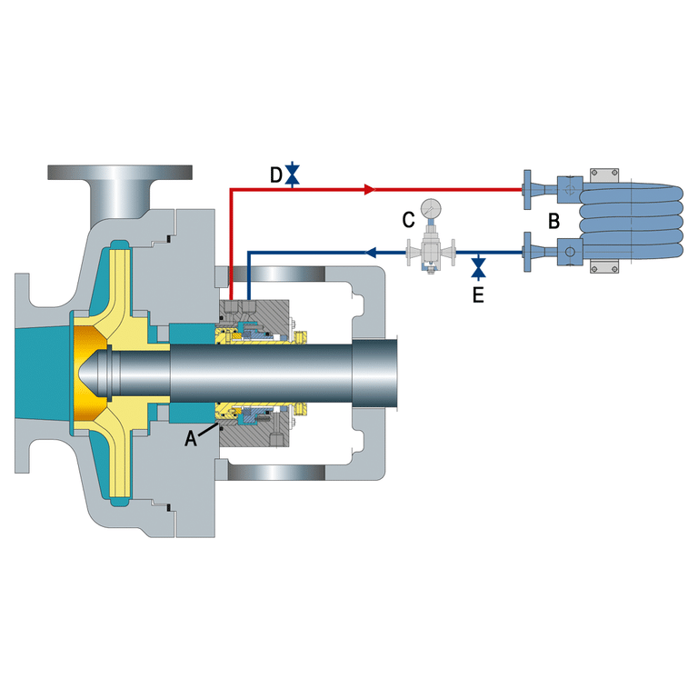
An undersized pot with properly sized connections will outperform an oversized pot with restricted flow paths. Thermosyphon circulation depends entirely on the density difference between hot fluid leaving the seal and cool fluid returning from the pot — any flow restriction kills circulation velocity.
Minimum Pipe and Tubing Sizes
Use a minimum of 1/2-inch pipe or 3/4-inch tubing for seal-to-pot connections. Smaller sizes create excessive friction losses that stall thermosyphon flow. I’ve pulled apart systems where engineers ran 3/8-inch tubing to save space, and the barrier fluid was not circulating at all — the sight glass on the return line showed zero flow despite the vendor’s assurance that “circulation is happening.”
Slope and Elevation Requirements
Maintain a minimum slope of 1:10 from the seal to the pot for natural circulation. The pot centerline should sit at least 18 inches (500 mm) above the seal chamber. This elevation head drives the thermosyphon loop — reduce it, and circulation rate drops proportionally.
Tubing vs. Piping
Tubing can eliminate every threaded joint between the seal and pot, leaving connections only at the seal gland and pot nozzles. In moisture-prone environments, carbon steel pipe is a liability — internal scaling can detach and lodge in seal faces or obstruct orifices. Stainless steel tubing avoids both problems.
All controls and instruments must be accessible from ground level. Block-and-bleed gauge configurations allow safe component swaps without decommissioning the system. Omitting block-and-bleed valves forces full system shutdowns for a simple gauge replacement — a design choice that costs more in lost production than the valves ever would.
When Standard Pot Sizes Fall Short
API 682 covers pump shaft diameters from 0.75 to 4.3 inches, with Category definitions referencing pressure limits of 300 to 600 psig and temperature limits of 350 to 750 F. Outside these boundaries, the default sizing rules do not apply. Engineers must calculate from first principles.
Out-of-Scope Applications
Large vertical pumps, high-speed compressor seals, and reactor agitator seals regularly fall outside API 682’s shaft size range. For these applications, the 3-gallon/5-gallon lookup table is meaningless. Start with the heat load calculation, add thermal expansion and leakage reserves, then verify that the selected vessel’s surface area provides adequate heat rejection.
High Heat Load Scenarios
Even within API 682 scope, certain combinations overwhelm default pot sizes. A moderate 2-inch seal at 600 F and 3600 rpm generates heat loads that a 3-gallon pot simply cannot dissipate through its surface area. The volume might technically hold enough fluid, but the vessel’s external surface area limits heat transfer to ambient. In these cases, either upsize the pot to increase surface area, add a cooling coil, or switch to a Plan 53A, 53B, or 53C configuration with external cooling.
The API 682 standard specifies defaults for a reason — they work for moderate conditions. But treating them as the final answer rather than a starting point is the single most common sizing error I encounter. Run the heat soak calculation. Check the 28-day leakage volume. Verify the surface area. The math takes thirty minutes and prevents failures that cost thousands.
Sizing Verification Checklist
Before finalizing any seal pot specification, verify these five items:
- Heat load (corrected with multipliers) falls within the pot’s heat rejection capacity based on surface area, not just volume.
- Total volume (heat sink + thermal expansion + 28-day leakage reserve) does not exceed 85% of the vessel’s gross capacity, leaving gas space for pressurization.
- Connection sizes meet the 1/2-inch pipe / 3/4-inch tubing minimum, with 1:10 slope and 18 inches of elevation head above the seal.
- The selected vessel geometry favors heat dissipation — a shorter, wider pot rejects more heat than a tall, narrow one of equal volume.
- For applications outside API 682 scope or above 400 F process temperature, calculations replace defaults entirely. Document the basis of design for the next engineer who inherits this system.
Confirm filling and pressurization procedures before commissioning the system.