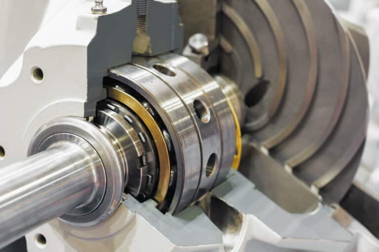
You are standing at a freshly installed Arrangement 3 dual seal. The 5-gallon seal pot is hung, the nitrogen header is connected, the barrier fluid is filled, and the commissioning checklist asks for two numbers before the pump starts: reservoir gas precharge and barrier fluid setpoint.
Reservoir, pumping ring, dual faces, nitrogen cap — the schematic itself is standard across every pressurized dual-seal plan (see the full API flush plan overview for siblings). What the spec sheet doesn’t tell you is how to land those two numbers correctly — and why the right answer shifts with ambient temperature, heat load, and barrier fluid choice. If you are still choosing between 53A, 53B, and 53C and have not yet decided which of the three is right for your service, the Plan 53A vs 53B vs 53C comparison walks the trade-offs (bladder vs piston accumulator, pressure ceiling, response time); this page assumes 53A is the chosen plan and focuses on the precharge and setpoint calculations that determine whether a 53A install actually performs.
How Plan 53A Circulates Barrier Fluid
Nitrogen-Pressurized Reservoir and the Pumping-Ring Loop
Plan 53A holds clean barrier fluid in an external reservoir under nitrogen pressure, and an internal pumping ring on the seal cartridge circulates that fluid through the dual-seal cavity and back. The reservoir sits above the seal so gravity primes the loop; nitrogen above the fluid provides the pressure differential against process pressure. Per API 682, Plan 53A Arrangement 3 configurations are 3CW-FB, 3CW-BB, and 3CW-FF — face-to-back or back-to-back cartridges where the inboard face sees barrier fluid, not process fluid.
The Reservoir as a Passive Settling Chamber
The reservoir does more than store volume. Wear particles, contamination, and any process leakage that crosses the inboard face settle to the bottom of the pot, away from the pumping-ring suction.
Treat the reservoir as a passive settling chamber, not a holding tank — that is the single mechanical advantage Plan 53A holds over the bladder-equipped 53B and 53C variants. Plans 53B and 53C close the loop and add a particle filter, but lose the gravity segregation a quiet reservoir gives you for free.
The Bladder Accumulator: Why 53A Doesn’t Have One
Henry’s Law and the 150 psig Dissolved-Gas Ceiling
Plan 53A pressurizes the barrier fluid with nitrogen in direct contact — there is no bladder between gas and fluid. The bladder accumulator belongs to Plans 53B and 53C, and that one design choice is the reason API 682 caps Plan 53A around 150 psig in the first place.
Henry’s Law governs the outcome: gas dissolves into liquid in proportion to pressure. Push nitrogen above 150 psig in direct contact with PAO or polyglycol barrier fluid and you store dissolved gas the same way a soda bottle stores CO2.
When the pot is depressurized — during refilling, instrument isolation, or shutdown — that dissolved nitrogen comes back out of solution. Bubbles form at the pumping-ring suction, circulation collapses, the seal faces dry-run, and you replace a primary seal that was operating perfectly an hour earlier.
The 53B/53C Bladder Trade-Offs
The bladder accumulator isolates gas from fluid and eliminates that failure path; the trade-off is that 53B and 53C give up the settling-chamber advantage and inherit a new failure mode of their own. A 53B or 53C bladder must be precharged to roughly 90% of the minimum barrier setpoint, and the maximum barrier pressure must stay below 4× the precharge.

Over-precharge drives the bladder into the poppet during discharge; charging too quickly extends the bladder longitudinally to the full shell length. Both faults destroy the bladder on the first pressure cycle.
Commissioning Setpoint and the Top-Up Trap
Barrier Pressure Setpoint: 1.4 Bar Above Chamber
Set barrier pressure at least 1.4 bar (20 psi) above the maximum seal chamber pressure, with a practical minimum of 1.5 to 2 barg even on low-pressure services. API 682 4th Edition specifies the 1.4 bar minimum; field practice often runs 10% above process pressure as a working margin. Before pressurizing, drain the pot, isolate the gas supply, and bleed the loop — the same vent procedure described in the seal pot filling and pressurization guide keeps you from trapping air at the pumping-ring suction.

The Ambient-Temperature Top-Up Trap
The single most expensive operator error on a Plan 53A is topping up at the wrong ambient temperature. The standard does not address this.
Refill the pot to 60 psig on a 5°C morning and as the day warms to 25°C, nitrogen expansion pushes barrier pressure 8 to 10 psig above the design point. Refill at 35°C and overnight cooling drops barrier below the 20 psi ΔP minimum.
Below ΔP, the system silently converts to Plan 52 behavior: process fluid leaks inboard across the primary face, contaminates the barrier, and the failure looks like a seal defect days later. Diagnose this by logging ambient temperature at every refill; if you cannot, run a fixed-fixed pressure strategy with a larger accumulator instead of a floating one.
The 28-Day Refill Acceptance Test
A useful commissioning acceptance test comes from Brandon Eckardt at the Fluid Sealing Association: the time between refills should be at least 28 days. API 682 requires a 2× safety factor on leakage rate when sizing the support system, and 28 days is the resulting acceptance criterion. Less than 28 days does not mean the support system is undersized — it means the primary seal is leaking more than expected.
Sizing the Pressure and Heat-Load Envelope
The 150 psig Ceiling Is a Temperature Envelope, Not a Wall
The 150 psig API ceiling is a temperature-conservative number, not a hard wall. Ahmed Sarwat at Heidelberg Materials documents direct-contact gas pressurization safe to 300 psig (21 barg) provided barrier fluid temperature stays below 250°F (120°C).

The constraint is gas solubility, which falls as temperature rises and rises with pressure — at hot barrier temperatures the dissolved-gas inventory at 150 psig is no different from cold barrier at 300 psig. Treat the ceiling as a temperature envelope: 100–150 psig as the conservative installation default, 300 psig achievable when you can prove barrier temperature stays under 250°F across all operating conditions.
Reservoir Volume and Pressure-Strategy Trade-Offs
Reservoir volume and cooling sizing are well-documented: 1 to 5 gallons of barrier fluid capacity (ISO VG 32 to 46 polyalphaolefin or polyglycol for most pump services), and 1 to 3 gpm cooling water through the integral coil.
Pressure strategy is the deciding sizing variable. A fixed-fixed strategy — fixed refill alarm, fixed full setpoint — needs a 10-gallon accumulator to hold pressure variation inside the ΔP window.
A floating strategy that adjusts setpoint to ambient gets the same control with a 5-gallon pot, but it asks operators to do arithmetic at every refill. Plants that have lost seals to the top-up trap pick fixed-fixed and pay for the larger pot.
Heat-Load Ceiling and the 1,800 rpm Shaft-Speed Floor
Heat load is the constraint pressure ceilings rarely catch first. The pumping ring depends on shaft speed; below 1,800 rpm, Mark Savage’s FSA work shows pumping-ring circulation often cannot carry seal-face heat away even with adequate cooling water. Field experience puts the 53A heat-load practical ceiling around 8 to 12 kBtu/hr — above that, an external pump (Plan 54) moves heat better than any pumping ring will.
When 53B, 53C, or 54 Is the Better Choice
Plan 53A is the right answer for steady barrier pressure under 150 psig at moderate heat load with a nitrogen header on site. Move up when one of those constraints breaks.
Conversion Triggers That Force the Plan Decision
The conversion triggers below are the numeric thresholds that force the call — each row identifies the specific constraint and the plan that solves it (full 3-way matrix: Plan 53A vs 53B vs 53C comparison).
| Trigger | Move to | Why |
|---|---|---|
| Sustained barrier pressure > 150 psig (or > 300 psig with hot barrier) | 53B | Bladder eliminates gas entrainment at higher pressures |
| Remote site, no nitrogen header available | 53B | One-time precharge, no continuous gas supply |
| Process chamber pressure swings widely | 53C | Piston intensifier tracks chamber, holds ΔP automatically |
| Heat load > 8–12 kBtu/hr or shaft speed beyond standard pumping-ring range | 53B with cooler, or 54 | Plan 53A pumping ring loses head margin; mechanized circulation needed |