
What is API Plan 13
API Plan 13 is a standard piping arrangement for mechanical seals, as defined by the American Petroleum Institute (API). It recirculates process fluid out of the seal chamber, through a flow control orifice, and back to the pump suction.
That direction is the whole point. Plan 11 feeds the chamber from discharge; Plan 13 drains it to suction. No reservoir, no cooler, no external utility.
How Does API Plan 13 Work
On a vertical pump the seal chamber sits above the impeller, which makes it the high point of the wetted path. Vapor and air collect there. Plan 11 cannot clear that pocket, because its flow arrives at the chamber rather than leaving it.
Plan 13 takes the connection at the top of the seal chamber and routes it down to the suction nozzle. The pressure difference between chamber and suction drives the flow, and the orifice sets the rate. The moving fluid does two jobs at once: it carries frictional heat away from the faces, and it continuously vents whatever vapor accumulates at the chamber.
The consequence is the defining property of the arrangement. With the chamber open to suction, seal chamber pressure is pulled down toward suction pressure, though it must stay above suction for the flow to run. Every other design decision on a Plan 13 seal follows from that.
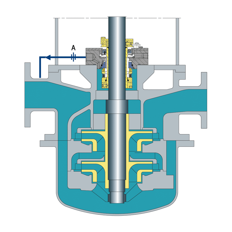
Design of API Plan 13
- Chamber Outlet Connection: Taken at the top of the seal chamber, the high point where vapor collects. Connecting anywhere lower leaves the pocket in place and the venting function is lost.
- Flow Control Orifice: Sits in the return line and sets the recirculation rate off the chamber-to-suction pressure difference. Undersize it and the faces starve; oversize it and the chamber loses the little pressure margin it has.
- Return Line to Suction: Routed continuously downward to the suction nozzle so the line itself cannot trap the vapor the plan exists to remove.
- Throat Bushing: Restricts flow between the impeller and the chamber so recirculation actually sweeps the seal faces instead of short-circuiting past them.
- No External Utilities: No reservoir, no cooler, no cooling water, no instrument air. If the specification calls for any of those, the arrangement is not a Plan 13.
Advantages of API Plan 13
- Simple Design: One line, one orifice, no external utilities to install, power, or maintain.
- Solves Venting: It is the standard answer for a vertical seal chamber that traps vapor, which is a failure mode Plan 11 cannot address on its own.
- Suitable for Clean Fluids: Plan 13 works well with clean, non-abrasive fluids that are compatible with the seal materials.
Disadvantages of API Plan 13
- Limited to Clean Fluids: Plan 13 tolerates moderate solids but is not suitable for abrasive particles or anything that can clog the flow control orifice.
- Dependent on Pump Operation: The recirculation is driven by the pump’s own pressure difference, so if the pump stops, the flush stops.
- Low Chamber Pressure: Pulling the chamber down toward suction pressure leaves little margin above the fluid’s vapor pressure. On volatile or near-saturated service that margin is the constraint, and Plan 14 adds a discharge-side leg precisely to restore it.
Applications
API Plan 13 is the standard recirculation arrangement for vertical pumps, where the seal chamber sits above the impeller and must be continuously vented back to the pump suction. It is the right choice for:
- Vertical in-line and vertical turbine pumps with seal chamber pressure above suction pressure
- Clean, non-flashing process services across chemical processing, refining, and petrochemical pump trains
- Single mechanical seals where seal-chamber pressure exceeds suction pressure