What is API Plan 21
API Plan 21 is a standard piping arrangement used with mechanical seals to control the environment around the seal. It’s part of a series of API (American Petroleum Institute) Piping Plans that provide guidelines for using mechanical seals reliably and safely.
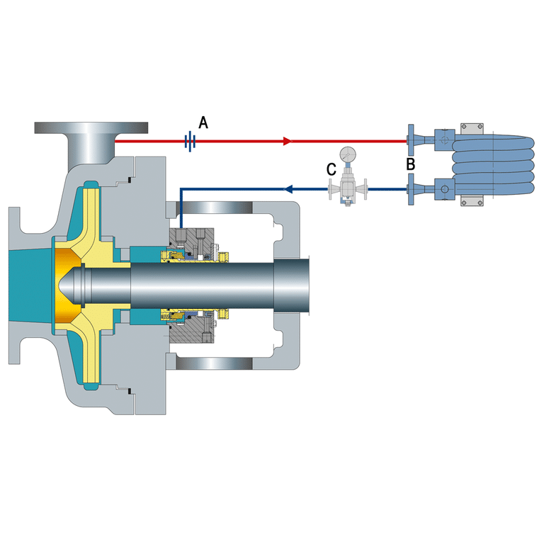
In an API Plan 21 system, the mechanical seal is cooled and lubricated by fluid from the pump. The fluid is taken from the pump discharge, cooled by a heat exchanger, and then directed to the seal chamber. After lubricating and cooling the seal, the fluid flows back into the pump casing through the seal chamber throat.
How Does API Plan 21 Work
In API Plan 21, a small stream of the pumped fluid is taken from the pump discharge (outlet) and sent to the seal chamber through a flow control orifice. The orifice limits the flow to 1-2 gallons per minute (3.8-7.6 liters per minute).
The fluid from the pump discharge, cooled in the heat exchanger, enters the seal chamber and flows around the mechanical seal. This cools the seal and lubricates the contact faces between the stationary and rotating parts. The fluid also helps to flush away any small particles or debris that might damage the seal faces.
After circulating through the seal chamber, the fluid flows back into the pump casing through the seal chamber throat and rejoins the process stream. This completes the circulation loop.
Design of API Plan 21
- Flush Line from Pump Discharge: a small-bore line taps process fluid off the pump discharge and routes it to the seal chamber — Plan 21 uses the pumped fluid itself, not a separate cooling liquid.
- Flow Control Orifice: sized to limit the flush to roughly 1–2 gpm (3.8–7.6 L/min), setting how much fluid reaches the seal faces.
- Heat Exchanger (Cooler): an in-line cooler between the discharge tap and the seal chamber drops the flush temperature before it reaches the faces — the feature that distinguishes Plan 21 from the un-cooled Plan 11.
- Seal Chamber Inlet and Return: the cooled flush enters the seal chamber, passes across the faces, and flows back into the pump casing through the seal chamber throat — an open, once-through path with no reservoir and no separate circulating pump.
Advantages of API Plan 21
- Cool and Clean Flush: Directs a fluid to seal faces, ensuring lubrication and cleanliness to prevent premature wear.
- Heat and Particulate Removal: Flush fluid removes heat and particulates, protecting seal faces from damage and extending their lifespan.
- Improved Fluid Vapor Margin: Maintains a higher fluid vapor margin, preventing vapor bubble formation and seal damage.
- Reduced Coking, Polymerization, and Fouling: Mitigates issues like coking, polymerization, and fouling, keeping seal faces clean.
- Self-Venting Design: Prevents air accumulation in the seal chamber, ensuring optimal sealing conditions and preventing damage.
Disadvantages of API Plan 21
- Cooler: API Plan 21 uses a cooler to remove heat from the seal flush fluid, but it has drawbacks like high energy consumption and high cooler heat duty.
- Clogging: Viscosity increase in the process fluid can lead to clogging issues, hindering proper flush flow and risking seal damage.
- Maintenance: Plan 21 systems have more components, requiring regular tasks like cleaning the cooler, checking flush flow, and inspecting for leaks or deterioration every 6 to 24 months.
Applications
- Chemical Processing
- Oil and Gas
- Pharmaceutical Manufacturing
- Food and Beverage
- Power Generation