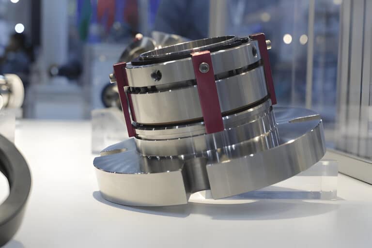
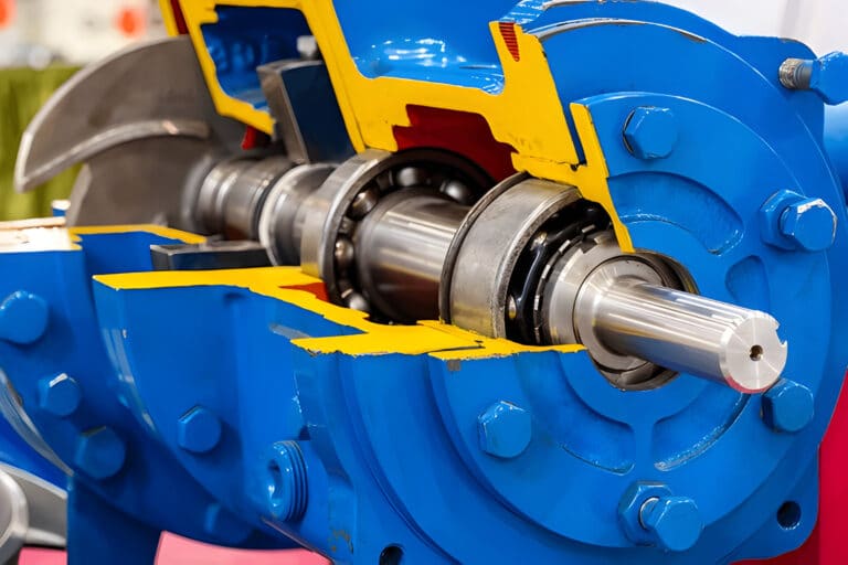
Every mechanical seal needs the right environment to survive — not just good face materials. Seal support systems are the piping configurations that control temperature, contamination, and pressure around the seal faces. I have pulled apart seals that looked perfectly specified on paper but failed in months because nobody thought through the support system.
API 682 defines 27 piping plan configurations, but memorizing plan numbers is the wrong starting point. Start with what your seal needs to survive, and that comes down to four functional categories: flush, quench, buffer fluid, and barrier fluid.
What Seal Support Systems Do
A seal support system delivers the right fluid, at the right temperature and pressure, to the seal chamber. API 682 sets a target of at least three years of uninterrupted service, and reaching that benchmark depends more on the support system than on the seal itself.
All 27 API piping plans fall into four categories based on what problem they solve:
- Flush systems (Plans 01, 02, 11, 13, 14, 21, 23, 32, 41) circulate clean, cool fluid across the seal faces for temperature and contamination control on single seals.
- Quench systems (Plans 62, 65) protect the atmospheric side of the seal — preventing crystallization, coking, or hazardous vapor release on the outside.
- Buffer fluid systems (Plan 52) provide an unpressurized secondary fluid between dual seal faces, serving as lubricant and leak detection medium.
- Barrier fluid systems (Plans 53A, 53B, 53C, 54) pressurize a secondary fluid above process pressure, ensuring zero process fluid escapes to atmosphere.
This functional grouping answers the question maintenance engineers actually ask: “What does my seal need to survive in this application?”
Flush Systems
Flush systems circulate fluid through the seal chamber to remove heat, wash away particulates, and maintain a stable fluid film. Most single seal installations use some form of flush plan.
Internal Circulation Plans
The simplest approach recirculates the pumped fluid itself. Plan 11 takes a tap from pump discharge and routes it through the seal chamber — effective when the process fluid is clean and below about 80 C. Plan 13 reverses the direction, flowing from seal chamber to pump suction, which works better for fluids with suspended solids because it sweeps particles away from the faces.
When temperature is the main concern, Plan 21 adds a heat exchanger to the Plan 11 flow path, and Plan 23 creates a closed-loop thermosiphon circuit with a cooler. Plan 23 is my default recommendation for hot services because the closed loop keeps contaminants out while thermosiphon circulation requires no external pumping.
External Flush Plans
When the process fluid is too dirty, too hot, or too aggressive for self-flushing, Plan 32 injects clean fluid from an external supply directly into the seal chamber. This is common in slurry pumps, paper stock applications, and anywhere the pumped fluid would destroy seal faces in weeks.
The most common mistake I see is treating flush systems as set-and-forget. Operators restrict flush flow during hot standby to save water or prevent pump cooldown, then wonder why the seal fails on the next startup. If you skip continuous flush during standby on a hot pump, you will be back pulling that seal within weeks.
Quench and Containment Systems
Quench systems work on the atmospheric side of the seal, not the process side. They solve a different problem: what happens to leakage that passes the primary seal faces.
Plan 62 delivers a quench fluid — typically steam or water — to the outboard side of a single seal. This prevents crystallization in sugar processing, coking in hot hydrocarbon services, or ice formation in cryogenic applications. Plan 65 adds a liquid reservoir on the atmospheric side for leakage collection and visual level indication.
Quench plans don’t improve sealing performance. If you need to prevent process fluid from reaching atmosphere entirely, you need a dual seal with buffer or barrier fluid, not a quench.
Buffer and Barrier Fluid Systems
This is where support system selection becomes a genuine engineering decision, and where I see the most expensive mistakes.
Buffer Fluid Systems
Plan 52 uses an unpressurized buffer fluid between the inboard and outboard seal faces of a dual unpressurized arrangement. The buffer fluid pressure sits below process pressure. A pumping ring driven by shaft rotation circulates buffer fluid from a reservoir through a heat exchanger and back.
If the inboard seal fails, process fluid leaks outward into the buffer fluid — detected through level changes, discoloration, or pressure shifts. This is acceptable for non-hazardous fluids where leakage triggers a planned maintenance response, not an environmental incident.
Barrier Fluid Systems
When the process fluid is toxic, flammable, or cannot reach atmosphere under any circumstances, you need barrier fluid pressurized above process pressure. The pressure differential forces barrier fluid inward across the inboard seal. Even if the inboard seal deteriorates, barrier fluid leaks into the process rather than process fluid leaking out.
Plan 53 has three subtypes based on how you maintain that pressure:
- Plan 53A uses an external pressure source — a gas bottle or plant nitrogen — to pressurize the reservoir. Barrier fluid pressure is set a minimum of 20 to 25 psi above maximum seal chamber pressure.
- Plan 53B uses a bladder accumulator for self-regulating pressure, suited for fluctuating process environments.
- Plan 53C employs a piston accumulator for extreme pressure applications.
Plan 54 delivers barrier fluid from a completely external system — a separate pump, reservoir, and cooling loop.
Before you start specifying barrier fluid systems, make sure the barrier fluid itself is correct. I have worked on Crude Vacuum Bottoms pumps at a refinery that had been chronic bad actors for seal life — decades of failures. The seals were fine for the service. The support system was the problem: compressor oil as barrier fluid. Compressor oils are not heat transfer fluids. The barrier fluid overheated, the inner seals cooked, and the piping was undersized carbon steel that didn’t meet API 682 requirements. Switching to a proper synthetic heat transfer oil and upgrading the piping solved what twenty years of seal replacements could not.
Leak Detection Plans
API 682 4th Edition introduced Plans 66A and 66B — the newest evolution in seal support, moving beyond environmental control into active monitoring.
Plan 66A installs a close-clearance bushing between the stationary seal face and drain cavity. As the seal begins to fail, the bushing restricts flow and raises upstream pressure. A pressure transmitter monitors this cavity for early warning before the leak becomes visible.
Plan 66B uses an orifice plug in the drain port — 1.5 mm bore for clean, low-viscosity fluids and 3 mm for dirty or high-viscosity fluids. It requires no additional space beyond a conventional seal, making it ideal for field retrofits, though it offers lower sensitivity than 66A.
These plans layer on top of flush or barrier systems, giving you lead time to plan a shutdown rather than reacting to catastrophic failure.
How to Match Your Application to the Right Category
Before you pick a plan number, answer these questions about your application:
| Question | If Yes | Support System Category |
|---|---|---|
| Is the process fluid clean and moderate temperature? | Single seal sufficient | Flush system (Plans 11, 13, 21, 23) |
| Is the process fluid dirty, hot, or chemically aggressive? | Single seal with external clean flush | Flush system (Plan 32) |
| Does leakage crystallize, coke, or freeze on the atmospheric side? | Single seal + atmospheric protection | Quench system (Plans 62, 65) |
| Is the fluid non-hazardous but requires secondary containment? | Dual unpressurized seal | Buffer fluid (Plan 52) |
| Is the fluid toxic, flammable, or zero-emission required? | Dual pressurized seal | Barrier fluid (Plans 53, 54) |
The condition dictates the seal arrangement, the arrangement dictates the support category, and the category narrows your options to two or three plans. From there, a step-by-step selection guide handles final plan selection based on available utilities, shaft speed, and space constraints.
Budgeting Support Systems: CAPEX Is the Smallest Layer
Equipment cost is the line item buyers focus on, and it is consistently the smallest piece of total ownership. A Plan 11 system is essentially an orifice and short piping. Plan 23 doubles the component count by adding a heat exchanger for thermosyphon cooling. Plan 32 requires panel-mounted instrumentation — shutoff valves, strainers, backflow prevention, flow indicators, pressure gauges. Dual seal plans (52, 53A/B) add reservoirs, accumulators, barrier fluid, and coalescing filters. The cost spectrum maps directly to containment capability, and skipping the instrumentation tier to save CAPEX is the most common reason buyers come back six months later with chronic seal failures and a retrofit bill larger than the original equipment.
Installation labor and piping typically equal or exceed the equipment cost itself. Dual seal systems are the worst offenders: barrier fluid reservoirs need elevation for thermosyphon circulation, accumulator pre-charges must be set precisely, and commissioning can take longer than the physical install — pressure verification, flow adjustment, instrument calibration. Procurement teams that quote only equipment regularly under-budget by 50% or more.
Operating cost is where uncontrolled flush plans become catastrophic. A single pump running Plan 32 at uncontrolled 20–30 gpm can consume 3 million gallons of water per year — annual water + wastewater costs can exceed the original equipment investment in the first year alone. The Fluid Sealing Association attributes 59% of premature seal failures to seal water issues, which reframes the budget: the flush system is not just an operating expense, it is insurance against seal replacement, unplanned downtime, and process contamination. Seals on uncontrolled flush systems last 6–18 months; properly managed systems extend life to several years. Flow meters, automated valves, and monitoring controls cut consumption by 90%+ and pay back in 6–12 months.
Budget every support system in three layers, not one: CAPEX (equipment + installation), commissioning (technician time for calibration), and annual OPEX (water, energy, maintenance, consumables). Compare options on 3–5 year total cost of ownership, not equipment price. A simpler plan genuinely costs less when the application allows it — but choosing a simple plan for a demanding application produces the most expensive outcome of all: repeated seal failures plus eventual system upgrade.
Choosing the Right Support System
Get the functional category right first — flush, quench, buffer, or barrier — and plan number selection becomes a straightforward engineering exercise. Get it wrong, and no amount of premium seal hardware will save you.
For most single seal applications, start with Plan 11 or 23 and escalate only when process conditions demand it. For dual seals, resolve the buffer-versus-barrier question first: if the process fluid absolutely cannot reach atmosphere, you need barrier pressure. Everything else follows from that one decision.
Add Plan 66A or 66B monitoring to any critical service where unplanned downtime costs more than the instrumentation. Early detection gives you the one thing maintenance teams never have enough of: time to plan the repair on your schedule, not the seal’s.