Are you responsible for maintaining pumps but intimidated by seal installation? Installing a cartridge mechanical seal doesn’t have to be complicated. Unlike traditional component seals that require extensive expertise and precise measurements, cartridge seals are pre-assembled units designed for faster, more reliable installation—even for operators with moderate experience.
This guide walks you through the complete process, from preparation through startup, ensuring your seal performs reliably and extends your equipment’s operational life. By following these steps carefully, you’ll install your seal right the first time.
What You Need to Know Before Starting
Required Tools and Materials
Before you start, gather these specific items. Most are standard maintenance tools you probably already have.
You’ll need a calibrated torque wrench—accuracy matters here. Lint-free cloths and a compatible solvent (usually mineral oil or alcohol) are essential for cleaning. Fine emery cloth smooths the shaft surface without scratching it.
The right lubricant is critical. Water-based lubricants like Pac-Ease work well for most installations, but check your seal manual. Some seals require specific lubricants or even dry installation. A setting clip removal tool (or simple screwdriver) removes the clips that hold the seal faces apart during shipping.
A dial indicator is optional but highly recommended. If your shaft alignment is off by even 0.005 inches, you’ll have problems.
Critical Safety Preparation
Before you touch anything, take these safety steps seriously. They’re not bureaucratic formalities—they prevent injuries and equipment damage.
Fully de-energize and lock out all power sources. Use a physical lock or tag on the main breaker. Don’t just turn things off. Close isolation valves and relieve all pressure in the pump casing. If the pump handles hazardous or hot fluids, drain it completely and flush the system. Allow equipment to cool to a safe temperature—hot metal transfers heat through tools directly to your hands.
Finally, verify you have the correct cartridge seal for your specific pump model and application. A seal designed for light oil won’t work on corrosive chemicals. Check the pump’s nameplate and cross-reference against your seal documentation or the pump manufacturer’s manual.
Pre-Installation Preparation: Setting Up for Success
Step 1: Inspect the Pump Shaft
Start by examining the shaft closely. Look for wear, corrosion, or existing grooves from old set screws. Any burrs (rough spots) or damage can tear the O-ring as you slide the new seal onto the shaft. This is the most common way cartridge seals fail during installation.
Run your fingernail along the shaft. If you feel sharp edges, you’ve found your problem. Mark these areas so you avoid them when positioning set screws later.
Step 2: Clean the Shaft Thoroughly
This step separates successful installations from leaking disasters. A dirty shaft is the single biggest cause of seal failure immediately after installation.
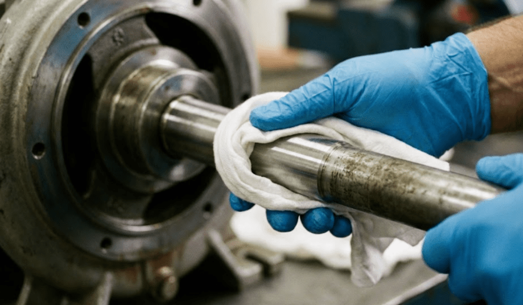
Use fine emery cloth to gently smooth the shaft surface. Remove any rust, oxidation, or debris. Work in small sections, checking frequently to ensure you’re not creating scratches. Light pressure is better than hard scrubbing.
Once smooth, wipe the shaft with a lint-free cloth dampened with compatible solvent. Do this repeatedly until the cloth comes away completely clean with no residue. Pay special attention to the area where the seal will sit and where set screws will grip.
Clean the seal chamber (stuffing box) too. Use the same cloth and solvent to remove old seal remnants, dirt, and any debris. A clean chamber means fewer contaminants work their way into your new seal.
Step 3: Check Shaft Alignment (Optional but Recommended)
Even small misalignments cause serious problems. When the shaft runs off-center, the seal faces don’t contact evenly. One edge wears quickly while the other stays fresh, and within days or weeks, your seal starts leaking.
If you have access to a dial indicator, mount it on the shaft and slowly rotate by hand. Watch the needle. Total indicated runout (TIR) should stay under 0.005 inches. If TIR exceeds 0.010 inches, you have significant misalignment that needs addressing before seal installation.
If your TIR is high, contact a technician for laser alignment. Spending two hours on shaft alignment now prevents two weeks of troubleshooting later.
Step 4: Apply Light Lubrication
Apply a thin film of water-based lubricant to the shaft. This reduces friction as the seal slides on and prevents damage to the O-ring during installation. Thick lubrication is worse than thin—excess lubricant collects dirt and creates friction instead of reducing it.
A thin film looks like a light sheen when you hold the shaft up to light. You should see almost nothing, but your finger should feel slightly slippery. That’s the right amount.

Installation Process: Step-by-Step Procedure
Step 1: Position the Seal on the Shaft
This is the most delicate moment. Gently slide the cartridge seal assembly onto the shaft, moving slowly and with control. The seal should slide smoothly onto the lubricated shaft.
Stop immediately if you feel resistance. Forcing it damages the O-ring irreversibly. If resistance happens, pull the seal back and inspect the shaft for unexpected burrs or rough spots. Never hammer or force a seal onto a shaft.
Many operators slide the seal onto the shaft, then discover the gland bolt holes don’t align with the pump’s threaded holes. To avoid repositioning, check alignment before sliding the seal completely home.
Step 2: Verify Gland Plate Alignment
Slide the seal until the gland plate meets the pump’s seal chamber face. The seal should sit flush—not tilted or crooked. Rotate the gland carefully until the bolt holes line up perfectly with the pump’s threaded holes.
This moment is critical. If the gland is tilted, even slightly, the bolts will pull it straight as you tighten, creating internal stress that distorts the seal faces. Take your time and get it right.
Step 3: Orient Flush and Vent Ports
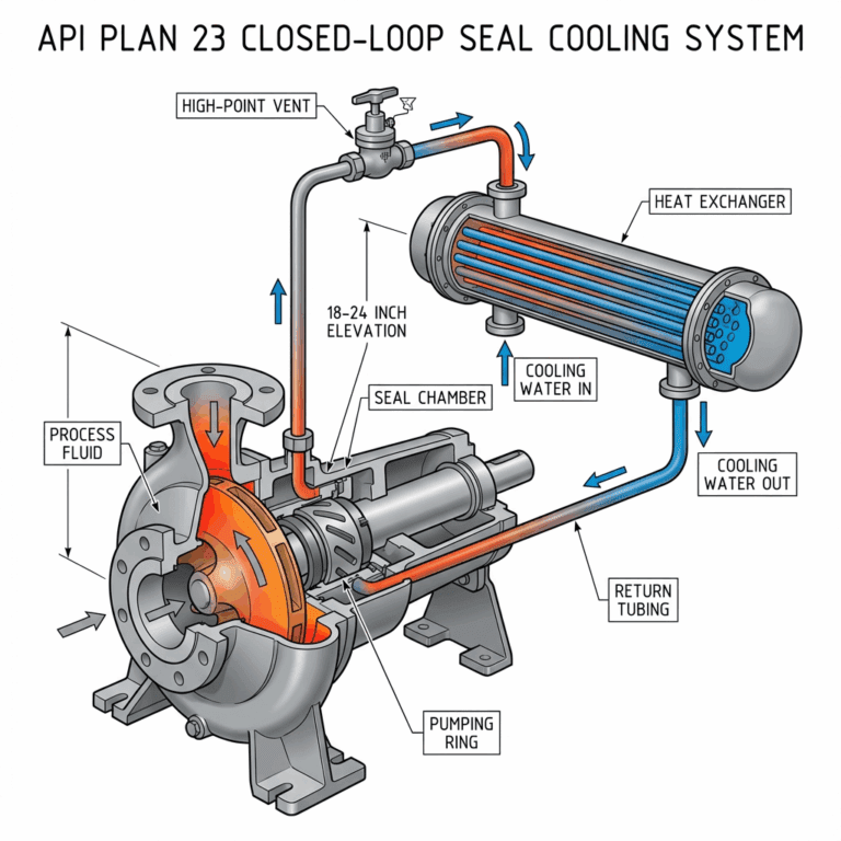
If your seal includes flush or vent ports (small tubing connections on the gland), position them according to the seal plan provided with your seal. Typically, these go at top dead center to ensure proper cooling and venting during operation.
Correct port positioning prevents air traps and ensures cooling fluid flows through the seal faces as designed. Air pockets create hot spots and seal failures.
Step 4: Hand-Tighten Bolts
Finger-tighten all gland bolts first. This secures the seal without applying pressure. Hand-tightening takes about 30 seconds and allows you to verify everything is positioned correctly before you apply torque.
As you tighten each bolt by hand, feel for resistance. If any bolt tightens much harder than others, stop and check for misalignment. The bolts should offer similar resistance when hand-tightened.
Step 5: Apply Torque in a Cross Pattern
Now comes the precision work. Using a calibrated torque wrench, tighten bolts in a diagonal (star) pattern. If you have four bolts, tighten positions 1 and 3, then positions 2 and 4. For six bolts, alternate around the circle.
Make multiple passes, gradually increasing pressure to the manufacturer’s specified torque. Start with 25 percent of final torque, then go to 50 percent, 75 percent, and finally full torque. This gradual approach distributes pressure evenly and prevents gland distortion.
Never jump to full torque in one pass. It’s tempting when you’re in a hurry, but rushing this step causes leaks. Follow the gradual approach religiously.
Uneven tightening is one of the most common mistakes. If you tighten bolt 1 fully, then bolt 2, the gland tilts slightly with each bolt. The final product is a crooked gland applying uneven pressure to the seal faces. Stick to the star pattern without exception.

Step 6: Set the Drive Collar or Set Screws
Most cartridge seals include a drive collar with multiple set screws that lock the rotating part of the seal to the shaft. Position these set screws over a clean, unmarred section of the shaft—away from old screw grooves if they exist.
Why? Set screws grip by biting into the shaft material. If they land on an old groove, they can’t grip effectively and will slip during operation. If you only have one set screw position option due to shaft length, offset the new screw to the side of the old groove.
Tighten set screws evenly. Turn each screw a few quarter-turns in succession rather than fully tightening one, then moving to the next. This applies pressure gradually and uniformly. A bolt that’s fully tight resists the next bolt tightening, creating uneven pressure.
Step 7: Double-Check All Connections
Verify that all bolts are at proper torque using your wrench one more time. Set screws should be firmly tight but not stripped. The seal should not move when you try to rotate it by hand.
Check that the seal hasn’t shifted or moved during tightening. Sight along the pump to ensure the gland isn’t tilted. If anything looks wrong, loosen all bolts and start the torque procedure again.
Critical Pre-Startup Steps
Step 1: Remove All Setting Clips
Setting clips hold the seal faces apart during transport and installation. They prevent the seal faces from grinding together during handling and shipping.
Remove ALL setting clips before operating the pump. This is non-negotiable. Setting clips left in place can fall back onto rotating parts during startup, potentially damaging the seal or creating an ignition source in spark-prone environments.
Most setting clips unscrew or unclamp easily. Look for small levers or fasteners on the gland. Remove each one and set them aside for future maintenance records.
Step 2: Manually Rotate the Shaft
By hand, rotate the pump shaft at least one full revolution. Feel for smooth, resistance-free rotation. Any binding, tightness, or grinding indicates a problem—stop and investigate.
Common causes of resistance include misalignment, over-tightened bolts distorting the gland, or a set screw bearing on a shaft surface in an unexpected location. Forcing it will damage the seal.
Smooth rotation feels easy, like turning a bicycle wheel. Resistance feels like turning a wheel with partially applied brakes. The difference is obvious once you feel it.
Step 3: Pressurize the System Slowly
Restart the pump at low pressure and gradually increase pressure to operating levels. Never jump to full operating pressure immediately. Most seal damage during startup happens when full pressure hits before the seal faces have settled into their running positions.
Start the pump and let it idle at 25 percent of operating pressure for two to three minutes. Gradually increase to 50 percent, wait another minute, then move to full pressure. This gradual pressurization allows the seal to adjust and settle.
Step 4: Monitor for Leakage
During the first 15 to 30 minutes of operation, monitor the seal for visible leakage. Some minimal seepage is normal initially—sometimes the seal needs a few minutes to fully seat. But steady dripping indicates installation problems.
If you see steady leakage, stop the pump immediately and investigate. Don’t run it hoping the leak goes away. It won’t. Identify the problem and fix it now.

When to Call a Professional
Contact a qualified seal technician if you experience persistent leakage after following this guide, suspect shaft misalignment issues, see signs of seal material damage or degradation, or need assistance with advanced seal arrangements or specialty applications. Some situations exceed the scope of basic installation, and professional help prevents costly mistakes.


