Roughly 30 to 40 percent of mechanical seal failures trace back to operating problems — and wrong seal type selection sits near the top of that list. I’ve seen plants blanket-switch every pump to bellows seals after a single hangup incident, only to discover six months later that bellows designs bring their own failure modes nobody warned them about. Both pusher and bellows seals fail. They just fail differently. Understanding those differences is the only reliable path to choosing the right design for your application. For the broader pusher-vs-any-non-pusher framing (including elastomer bellows and other non-sliding designs), see Pusher vs Non-Pusher Mechanical Seals.
How Pusher and Bellows Seals Work Differently
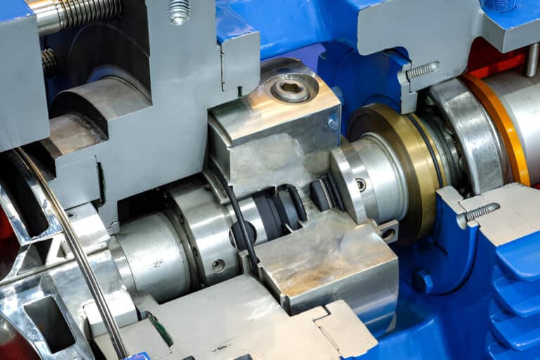
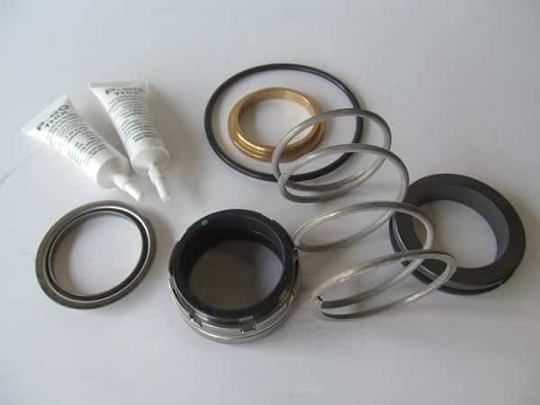
A pusher seal uses a spring-loaded elastomer O-ring that slides axially along the shaft or sleeve to compensate for wear and thermal movement. A bellows seal replaces that sliding O-ring with a flexible metal or elastomer element that deforms rather than translates — no sliding friction, no dynamic elastomer contact against the shaft.
API 682 Classification
API 682 codifies this split. Type A seals are pusher designs: reaction-bonded silicon carbide mating ring, carbon primary ring, fluoroelastomer O-ring, Hastelloy C springs, 316SS hardware. Type B seals are bellows designs, replacing the elastomer secondary seal with a flexible metal bellows element. The standard defaults to Type A for general service and reserves Type B for high-temperature, cryogenic, or chemically aggressive environments.
That default exists for a reason. Pusher seals handle the vast majority of standard pump applications reliably and economically. Bellows seals earn their place only when specific operating conditions demand them.
Pressure-Speed Tradeoff
O-ring pusher seals structurally handle higher pressures than metal bellows. Bellows seals perform better at elevated rotational speeds. Selection requires pressure-speed envelope analysis, not single-variable optimization. A pump running at high pressure and moderate speed may actually favor a pusher design, even in moderately aggressive service.
How Pusher Seals Fail
Seal hangup is the single most common failure mode in pusher designs, yet it rarely appears in selection guides. Hangup occurs when process fluid leakage accumulates and hardens beneath the floating O-ring element, cementing it to the shaft or sleeve. Once the O-ring loses axial movement, the seal face can no longer track normal shaft deflection or thermal growth. Face separation follows, then catastrophic leakage.
I’ve seen this failure pattern dozens of times in hot hydrocarbon and chemical services. The O-ring doesn’t fail from chemical attack alone — it fails because deposits from the process fluid lock it in place. Coking residue in refinery pumps, crystallized product in chemical transfer, scale buildup in cooling water: all produce the same result.
Fretting Damage
Even before full hangup, the sliding O-ring causes fretting on the shaft or sleeve surface. That fretting groove becomes a secondary leak path and accelerates elastomer degradation. In services where pusher and non-pusher designs are both viable, fretting damage is the maintenance cost that rarely shows up in the initial selection spreadsheet. Check shaft sleeves during every seal replacement — fretting grooves deeper than 0.1 mm mean hangup is already in progress.
How Bellows Seals Fail
Bellows seals eliminate hangup entirely. No sliding O-ring means no deposit buildup, no fretting, no loss of axial tracking. That advantage is real — bellows designs roughly double maintenance intervals compared to pusher seals in equivalent service, extending mean time between replacement from around 8,000 to 16,000 hours. But bellows introduce three failure modes that pusher seals cannot experience.
Fatigue Cracking
Metal bellows are prone to fatigue failure in flashing hydrocarbon service, induced by stick-slip when marginal vapor suppression occurs. Cyclic pressure fluctuations from flashing cause repeated bellows expansion and contraction, forming microscopic cracks that gradually propagate to failure. This happens in the exact application where bellows seals are most commonly specified — hot hydrocarbons where pusher seals hang up from coking. The irony is hard to miss.
Stress Corrosion Cracking
316L stainless steel is the default bellows material for chemical resistance. Yet peer-reviewed failure analysis has documented 316L bellows failing by stress corrosion cracking (SCC) in chloride-containing environments — cracks initiating from the outer surface and propagating inward, accelerated by residual thermal stresses from welding. The same material specified for chemical resistance has a specific chemical vulnerability. In chloride service, specifying a bellows seal with 316L bellows can be worse than a properly maintained pusher seal with a compatible fluoroelastomer O-ring.
Vacuum Lock on Restart
During shutdown, vacuum can form between seal faces. On restart, if that vacuum doesn’t break cleanly, torsional load transmits directly through the bellows, twisting and tearing it. Pusher seals handle this without issue — the spring mechanism provides sufficient breakaway force without transferring torque through the secondary seal. Bellows seals in intermittent service or frequent start-stop applications carry this risk unless the seal chamber design specifically addresses vacuum break.
The 4-Condition Selection Test
Stop choosing between pusher and bellows based on a single variable. Run through these four conditions in order — the first one that triggers a clear answer is your selection driver.
Condition 1: Temperature. Will the secondary seal environment exceed the continuous rating of fluoroelastomer O-rings (roughly 200 C / 400 F)? If yes, the pusher O-ring cannot survive — bellows required. If no, proceed to Condition 2.
Condition 2: Chemical compatibility. Does the process fluid attack elastomers but not the bellows material? Check specifically for coking, crystallizing, or polymerizing fluids that would cause hangup. If the fluid deposits solids on shaft surfaces, bellows preferred. But also check: does the environment contain chlorides or other SCC-inducing species that would attack the bellows material? If so, material selection becomes the true variable — not the pusher-versus-bellows choice.
Condition 3: Shaft movement and speed. High shaft deflection or runout favors pusher seals — their axial compliance range exceeds most bellows designs. High rotational speed favors bellows — no fretting, no dynamic O-ring drag. Map your pump’s operating envelope before defaulting to either type.
Condition 4: Maintenance economics. For standard services where Conditions 1 through 3 don’t force a clear answer, compare total cost of ownership. Bellows seals cost more upfront but roughly double the maintenance interval. A pump running 24/7 in clean, moderate-temperature service may justify the bellows premium through reduced downtime. A standby pump running intermittently probably doesn’t — and the vacuum-lock restart risk may actually make it a worse choice.
The API 682 standard specifies Type A (pusher) as the default for a reason. Bellows seals should be specified for cause, not defaulted to as an upgrade.
Making the Right Selection
The question shouldn’t be “pusher or bellows?” — it should be “what is my dominant failure risk?” A plant running hot hydrocarbons faces hangup as the primary threat, making bellows the correct answer. A plant running chloride-containing cooling water faces SCC as the bellows-specific threat, making a properly maintained pusher seal the safer choice.
Run the 4-condition test against your actual operating data. If temperature or chemical environment forces you to bellows, verify the bellows material against your specific fluid chemistry — especially chloride content. If nothing forces you away from pusher seals, the simpler, cheaper, higher-pressure-rated design is almost certainly the right one. The most expensive seal is the one that fails because nobody asked what would kill it first.