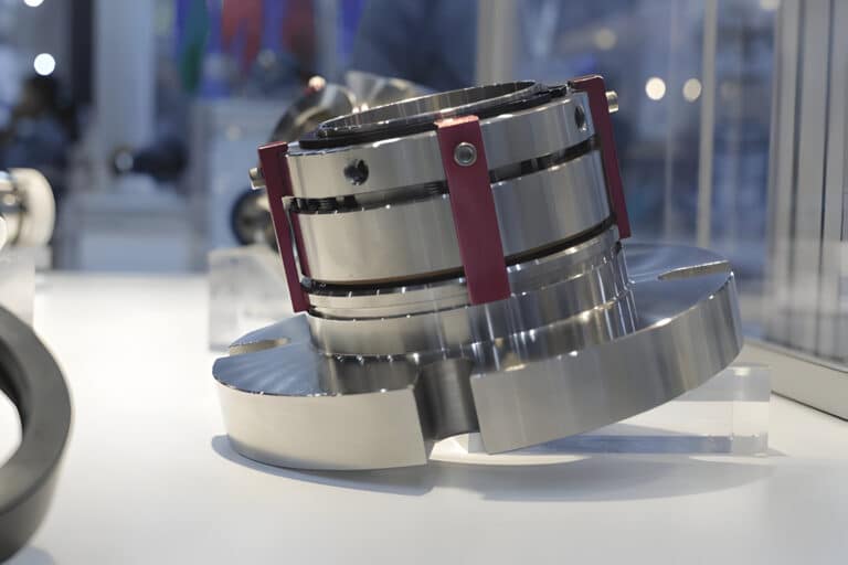
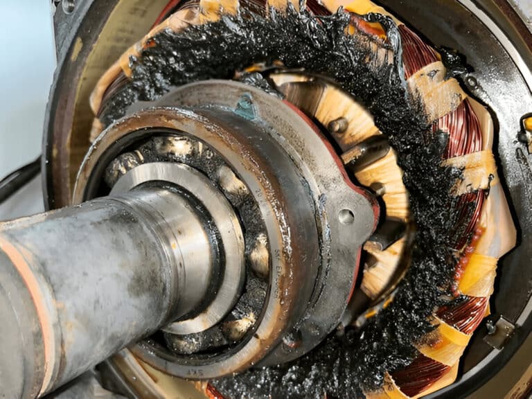
Every mechanical seal leaks. The fluid film between rotating and stationary faces is typically 1 micron thick — 75 times narrower than a human hair — and some process fluid crosses that gap by design. The difference between a functioning seal and a failing one is not whether leakage exists, but which path it takes and how fast it grows.
Most troubleshooting guides hand you a generic cause list and leave you to guess which applies. That approach fails at the primary sealing point because three distinct leakage paths exist there, each with different visual signatures and different corrective actions. I’ve seen this failure pattern dozens of times — a technician replaces the seal faces when the O-ring is the actual problem, guaranteeing a repeat failure within months.
How the Primary Seal Face Controls Leakage
Seal faces are lapped flat to within two helium light bands — about 23 microinches — before installation. Spring force and hydraulic pressure maintain a fluid film thin enough to limit leakage to roughly half a teaspoon per day on a typical water application.
That precision disappears under operating conditions. Thermal gradients, pressure distortion, and shaft deflection warp faces to ten light bands or more. Leakage responds to face separation with a cubical relationship: double the gap, and leakage increases eightfold. This sensitivity explains why a seal running fine for months can suddenly drip after a minor process upset — even a few microinches of additional separation produces dramatic results.
The primary seal is one of four sealing points in a typical mechanical seal assembly, and at this interface alone, fluid can escape through three separate paths.
Three Leakage Paths at the Primary Seal
Face Separation Leakage
Fluid escapes directly across the seal faces when the gap exceeds design film thickness. Three mechanisms drive face separation:
- Thermal distortion. Uneven heat bows one or both faces, shifting contact to a narrow band at the inner or outer diameter. Look for asymmetric wear tracks and heat discoloration on the carbon face.
- Hydraulic opening force. Excessive seal chamber pressure overcomes the closing force balance, producing uniform leakage that scales with discharge pressure. Check chamber pressure against the seal’s PV rating before assuming a face defect.
- Mechanical damage. Hard particle ingestion or handling damage creates radial scratches that act as channels. Unlike thermal or hydraulic leakage, scratch-driven leakage does not respond to operating condition changes.
The API 682 standard specifies face flatness requirements for a reason: faces outside tolerance cannot maintain the designed film thickness regardless of assembly quality.
Secondary Seal Bypass
This is where most misdiagnoses happen. The O-ring at the primary ring creates a static seal between the component and the shaft sleeve. When this elastomer degrades, fluid bypasses the faces entirely — flowing around rather than across them.
The diagnostic paradox: a seal with full 360-degree face contact and minimal wear can still leak steadily. Full contact with continuous dripping — whether the shaft is rotating or stationary — points to secondary seal failure, not face geometry. Nicked O-rings from installation, compression set from heat exposure, or chemical attack all create bypass channels that no amount of face correction will fix.
Test this by checking whether leakage continues with the pump stopped. Face separation leakage stops when rotation stops. Secondary seal bypass leaks regardless of shaft state.
Drive Mechanism Wear
The least obvious path. Drive pins, lugs, or set screws transmitting torque to the rotating component create a dynamic interface. As these wear, they permit micro-movement of the primary ring — intermittent face contact loss that appears and disappears with no clear pattern, often worsening under higher torque.
Inspect drive pins for elongated holes, worn flats, or fretting debris during disassembly.
Reading the Leak: What Each Pattern Tells You
A systematic approach works backward from observation, not forward from a cause list. Before disassembling anything, answer three questions.
Is This Leakage or Normal Operation?
Anything below one drop per minute (roughly 3 mL/hr) falls within the acceptable leakage range for most standard applications. Three drops per minute qualifies as a major leak under California regulatory standards.
Does It Leak With the Pump Stopped?
Stop the pump, wait ten minutes, observe. Continued dripping at the same rate points to O-ring degradation. Leakage that slows and stops implicates the faces.
Is the Leakage Steady or Intermittent?
Constant leakage suggests a fixed defect — face damage, O-ring nick, or permanent gap. Intermittent leakage that correlates with load changes points to thermal distortion or drive mechanism wear.
What Fleet Data Reveals
When I ran failure analysis across pump fleets, the pattern held: roughly half of primary seal leakage traced to secondary seal degradation, not the faces. Technicians who skipped the static test and went straight to face inspection wasted the rebuild. The contact pattern on removed faces showed full, even contact — the faces were never the problem.
Before replacing the seal, check the O-rings first. Document spring measurements and face condition before cleaning anything. Wrap mylar around shaft edges during removal to protect new elastomers from the very damage that caused the original failure.
Corrective Actions by Leakage Path
Fix-to-Path Mapping
A $50 O-ring solves a secondary seal bypass permanently. A $2,000 face upgrade does nothing for the same condition. The table below maps each path to its specific corrective action.
| Leakage Path | Primary Indicator | Corrective Action |
|---|---|---|
| Face separation — thermal | Asymmetric wear track, heat discoloration | Verify flush plan flow rate and temperature |
| Face separation — hydraulic | Uniform leakage proportional to pressure | Re-evaluate seal chamber pressure and closing force design |
| Face separation — mechanical | Radial scratches across sealing band | Replace faces; eliminate particle source |
| Secondary seal bypass | Full contact ring + steady static leakage | Replace O-rings; verify elastomer compatibility |
| Drive mechanism wear | Intermittent leakage under load | Inspect and replace drive pins/lugs; check shaft runout |
When the Path Diagnosis Is Wrong
I worked on an ammonia transfer pump at a cold storage facility that failed catastrophically less than a year after seal replacement. The team had replaced faces twice, convinced they had a face problem. Root cause analysis revealed piping sloped the wrong direction and tight elbows starving the seal of lubrication. The system forced the faces apart — not a face defect. Correcting the piping geometry solved it permanently.
What the spec sheet doesn’t tell you is that a seal selected to API 682 standards should deliver at least three years of uninterrupted service. If you replace seals annually, the path diagnosis is wrong. Check common failure patterns before ordering another replacement.
Prevention Starts With Path Awareness
The most effective change I have seen maintenance teams make is not buying better seals — it is learning to distinguish which path failed before ordering the replacement. A $50 O-ring replacement solves a secondary seal bypass permanently. A $2,000 face upgrade does nothing for the same condition. Run the static leak test, document the contact pattern, preserve the elastomers for inspection, and let the evidence select the corrective action.