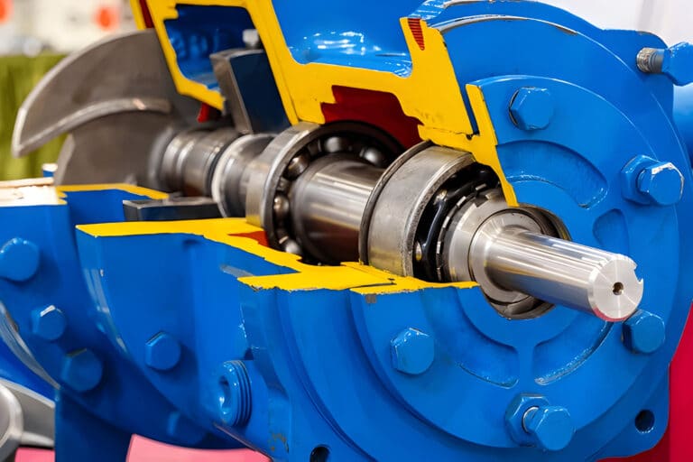
Every double mechanical seal I disassemble tells the same story: someone treated it like two single seals bolted together. It is not. A double seal has four sealing faces, a dedicated fluid system, and a gland plate engineered for pressurized service. Missing any of these distinctions during maintenance leads to repeat failures.
The components below are organized by function. Where a part differs from its single-seal equivalent, I call it out — because that is where maintenance mistakes start.
Seal Faces
A single mechanical seal has two sealing faces: one rotating, one stationary. A double seal doubles that count to four faces arranged in two sets — an inboard (process-side) set and an outboard (atmosphere-side) set.
The inboard faces contact process fluid directly. Material pairing here follows the same logic as single seals: silicon carbide against silicon carbide for abrasive slurries, carbon against silicon carbide or tungsten carbide for clean services. The outboard faces run in barrier or buffer fluid, which is a much cleaner and more controlled environment. This means you can sometimes use a less aggressive material pairing on the outboard set without sacrificing seal life.
What the spec sheet does not tell you is that the outboard faces are more vulnerable to contamination damage than the inboard faces. Barrier fluid that picks up particles from reservoir corrosion or degraded elastomers destroys outboard faces faster than process fluid destroys the inboard set. I have pulled outboard faces with scoring patterns that traced back to a neglected barrier fluid reservoir.
Inspection Points
Check all four faces during every seal changeout. Run a fingernail across each face — any catch means the lapping is gone. Never handle lapped faces with bare hands. A single fingerprint leaves enough oil residue to create a leak path across the contact band.
Secondary Seals, Springs, and Drive Components
O-Rings and Elastomers
A double seal carries roughly twice the O-ring count of a single seal. Each seal set has its own shaft O-ring and face O-ring, plus the gland plate requires additional static seals for the barrier fluid cavity. The outboard O-rings sit in barrier or buffer fluid continuously, so material compatibility matters on both the process and barrier fluid side.
Install every O-ring with a film of compatible lubricant. Dry installation tears elastomers — particularly FFKM compounds, which are stiffer than standard FKM and catch on shaft steps more easily.
Springs and Bellows
Each seal set needs its own closing force. In a pusher-type double seal, that means two independent spring packages. Multi-spring designs are common in double seals because they distribute load more evenly across both face sets.
The critical difference from single seals: spring orientation reverses between inboard and outboard sets depending on the arrangement. In a back-to-back configuration, both spring sets push outward from the center. In a face-to-back configuration, both springs push in the same axial direction. Getting this wrong during reassembly puts one seal set in tension rather than compression — and that set will leak on startup.
Drive Elements
Set screws, drive pins, or drive collars transfer rotation from the shaft to the seal’s rotating components. Double seals in cartridge format share a single sleeve but need drive elements for both seal sets. Verify that drive elements engage their slots fully. A partially seated drive pin on the outboard seal will not show symptoms during static testing but causes intermittent leakage under running conditions.
Gland Plate and Cartridge Hardware
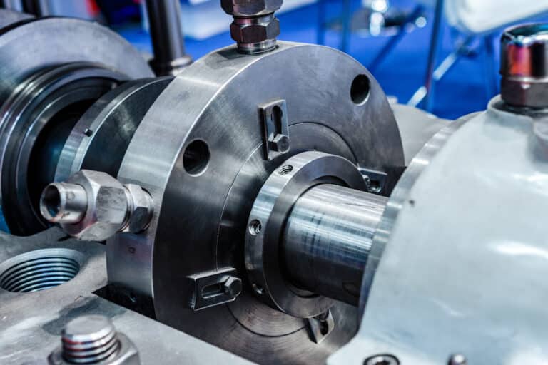
The gland plate on a double seal is fundamentally different from a single-seal gland. It must contain barrier or buffer fluid between the two seal sets, which means it has internal passages, additional ports for fluid supply and return, and instrumentation connections for pressure and temperature monitoring.
Over-tightening gland bolts distorts the plate and misaligns seal faces. I have seen this failure pattern dozens of times — a technician torques to “good and tight” instead of following the bolt pattern, and the outboard seal leaks within a week.
Cartridge Assembly Components
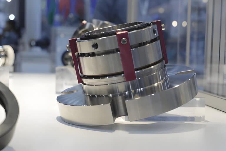
Most double seals ship as pre-assembled cartridge units with setting clips, centering tabs, and shipping spacers. These components must be removed before operation and reinstalled before any future disassembly. Ignoring the setting clips cost one plant two complete seal assemblies in a single shift — the technician ran the pump without removing the spacers, and both seal sets failed from locked rotation.
The cartridge sleeve itself is a structural component. It positions both seal sets at the correct axial spacing and provides the sealing surface for shaft O-rings. A scored or corroded sleeve creates a leak path that no amount of face lapping can fix.
Barrier and Buffer Fluid System
No single seal has one. The barrier or buffer fluid system is a multi-component subsystem — reservoir, pumping ring, instrumentation, piping — that defines how a double seal operates.
API 682 draws a hard line between two configurations. Arrangement 2 runs unpressurized buffer fluid between the seal sets (Plan 52). Arrangement 3 runs pressurized barrier fluid (Plan 53A). The component sets for each are different enough that spare parts do not interchange.
Plan 52 (Unpressurized Buffer) Components
- Reservoir with level gauge and pressure gauge
- Supply and return piping between reservoir and seal gland
- Internal pumping ring (mounted on the outboard seal’s rotating assembly) to circulate buffer fluid
- Alarm switches for level and pressure monitoring
The pumping ring is not unique to double seals; single seals also use one in a Plan 23 loop. It is a small impeller-like device that creates enough flow to circulate buffer fluid through the reservoir and back through the seal cavity, removing heat from both face sets.
Plan 53A (Pressurized Barrier) Components
Plan 53A adds several components that Plan 52 does not require:
- External pressurization source (nitrogen supply acting directly on the reservoir) maintaining 20-25 psig above maximum seal chamber pressure
- Cooling coil inside the reservoir for thermal management
- Higher-specification instrumentation (pressure transmitter, not just a gauge)
- Replenishment mechanism (hand pump or automatic makeup system)
The API 682 standard specifies this pressure margin for a reason. Barrier pressure must exceed process pressure at all times, or process fluid leaks across the inboard seal into the barrier fluid — defeating the entire purpose of the double seal.
How Arrangement Type Affects Components
The same basic component set gets physically reconfigured across three arrangement geometries. Ordering replacement parts from a generic component list without knowing the arrangement is how technicians end up with the wrong spring orientation or mating ring count.
Face-to-Back
One mating ring sits between the two flexible elements (rotating faces). This does not share a mating ring between seal sets; each set keeps its own. The inboard seal’s process fluid sits on the outer diameter of the faces, which centrifuges abrasive particles away from the sealing interface. API 682’s 4th Edition positions face-to-back as the default for Arrangement 2.
Back-to-Back
Both flexible elements mount between the mating rings, with springs loading outward in opposite directions. This arrangement requires independent spring sets for each seal and, like face-to-back, has no shared mating ring. The trade-off: installation is simpler because both seal sets are accessible from the gland end.
Unbalanced back-to-back seals require barrier fluid pressure at least 15 psig above seal chamber pressure. Balanced designs reduce this requirement but add hydraulic balance features to the face geometry — another component-level difference that affects spare parts specifications.
Face-to-Face
Both mating rings mount between the flexible elements. This is the most compact arrangement and fits tight axial spaces. The limitation is reduced barrier fluid volume between the seal faces, which limits heat dissipation and restricts this arrangement to lower-duty applications.
The Real Difference Between Single and Double Seal Components
Strip away the textbook definitions, and the practical difference comes down to three things. First, the barrier or buffer fluid system: a single seal does not have one. Every reservoir, pressure gauge, and supply line in that system is double-seal-specific. Second, the gland plate: a double-seal gland has internal fluid passages and instrumentation ports that a single-seal gland does not need. Third, the inspection scope: a double seal demands that you check four faces, twice the O-rings, two spring packages, and an entire fluid support system — none of which exists on a single seal.
Component knowledge without this context produces technicians who can name every part but still install the seal incorrectly. Know what each part does, know which parts are unique to double service, and know what to look for when you pull one apart. That is the difference between a component list and a maintenance skill.