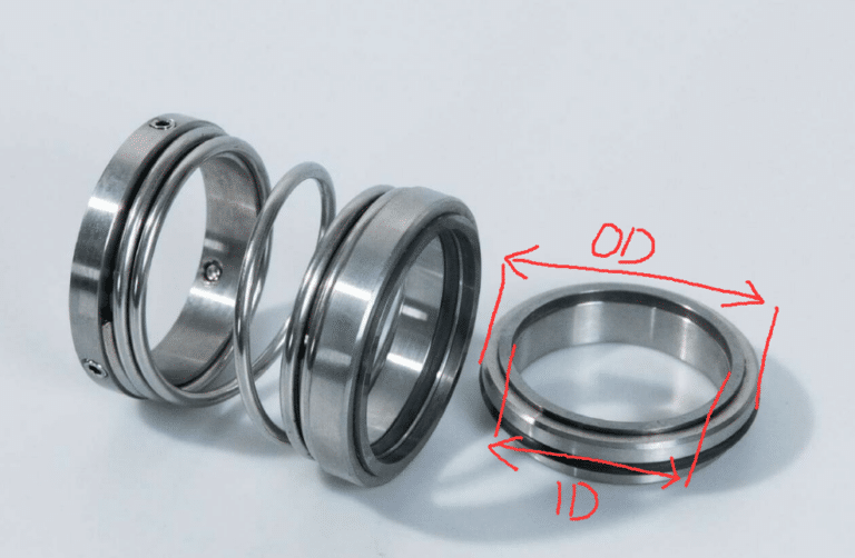
A maintenance engineer pulls a failed double seal from a chemical transfer pump. The faces look fine. O-rings are intact. He installs a new cartridge — and three months later the same pump is down again. The seal was never the problem; the barrier fluid reservoir had been losing pressure for weeks and nobody was watching the gauge.
Most double-seal failure diagnosis stops at the hardware and never reaches the support system. The barrier or buffer fluid system adds an entire failure domain that single seals do not have.
Industry estimates suggest roughly 80% of what gets classified as “seal failure” actually traces to support-system issues, operating conditions, or installation errors. Diagnosing a double seal without evaluating all three failure domains — seal faces, secondary seals, and the support system — guarantees repeat failures.
Why Double Seals Fail Differently Than Single Seals
A single seal has two failure domains: the seal faces and the secondary sealing elements. A double seal adds a third — the barrier or buffer fluid system — and that third domain changes the entire diagnostic approach.
Operating problems cause 30–40% of premature seal failures and installation errors another 20–30%. Double seals amplify both, because every support-system component (reservoir, thermosiphon piping, pressure source, instrumentation) becomes a potential failure origin that manifests as seal leakage.
The diagnostic trap is reflexive: a double seal leaks, corrective measures target the seal hardware. The reflex works for single seals; for double seals it misses the most common failure domain entirely.
The Three-Domain Model
Every double seal failure originates in one of three domains:
- Domain 1 — Seal faces: Wear, thermal distortion, vapor flashing, material attack. These are the failures that look like what you expect a “failed seal” to look like.
- Domain 2 — Secondary seals: O-ring degradation, elastomer extrusion, bellows fatigue. Primary faces get all the attention during teardown, so secondary-seal damage gets logged as a face problem.
- Domain 3 — Support system: Barrier fluid pressure loss, wrong fluid, contamination, piping restrictions, operational procedure errors. This domain does not exist in single seal arrangements and accounts for the majority of double seal field failures I investigate.
The corrective action depends entirely on which domain you identify. Replace the seal when the support system is the root cause, and you will be pulling it again within months.
Seal Face and Secondary Seal Failures
Damage patterns on the faces and the elastomer set tell you which side of the seal — process or barrier — drove the failure. They also tell you whether the root cause sits at the face interface or one ring deeper in the secondary seals.
Inboard vs Outboard Face Damage Patterns
In a back-to-back arrangement the inboard seal contacts process fluid and the outboard seal contacts barrier fluid. The damage pattern tells you which side the failure came from.
Inboard face damage — carbon blistering, chemical attack, abrasive scoring — points to process-side conditions: inadequate throat-bushing clearance, wrong face material, or process upset. Outboard face damage — heat checking, coking deposits, dry-running marks — points to barrier-fluid problems: low level, high temperature, or wrong viscosity. Replacing the outboard seal three times before anyone checks the reservoir cooling loop is the canonical version of this mistake; the corrective action is to fix the cooling, not the seal.
Thermal Distortion and Vapor Flashing
In volatile services, barrier fluid can flash to vapor between the seal faces. The force imbalance causes intermittent face separation but leaves no visible wear marks — pull the seal, find nothing, reinstall it, the leak returns.
Coking is negligible below 300 °F. Above that in hydrocarbon service, the primary sealing interface accumulates carbon deposits that prevent full face contact. The corrective action is improved heat removal from the seal chamber — upgrading the thermosiphon piping or switching to forced circulation — not changing face materials.
O-Ring and Elastomer Degradation
A degraded inboard O-ring lets process fluid contaminate the barrier cavity; a degraded outboard O-ring lets barrier fluid leak to atmosphere. Both show up as “barrier fluid loss” on pressure trending, but the contamination pattern in the drained fluid tells you which side failed.
Process contamination (color change, chemical smell, particulate) means inboard secondary-seal failure. Clean fluid with declining level means outboard secondary-seal failure or a system fitting leak. This five-minute check saves hours of teardown.
Barrier Fluid System Failures
The majority of double seal service calls trace back to this domain — the one that does not exist for single seals. Having the API 682 support infrastructure installed and having it functioning correctly are two different things.
Pressure-Related Failures
Barrier fluid must be maintained 1–2 Bar (15–30 psi) above process pressure; API Plan 53A systems require 20–25 psig above maximum process pressure. Pressure decay below this differential reverses the pressure across the inboard seal, pushing process fluid into the barrier cavity.
API Plan 52 (unpressurized buffer) systems tolerate inboard-seal failure — the outboard seal assumes primary duty and buys time before shutdown. API Plan 53A does not have this tolerance: barrier pressure loss affects both seals simultaneously because the pressurized barrier is what keeps the inboard faces loaded. The same pressure-loss symptom therefore requires different urgency depending on the piping plan.
Fluid Selection and Contamination
Barrier-fluid selection itself is a failure mode. Automotive and transmission oils have produced mixed results because their additive packages can attack seal-face materials. Oil viscosity must stay below 32 cSt at 40 °C — above that, flow resistance generates enough heat to cause thermal distortion.
Water-based fluids have three times the thermal conductivity and twice the specific heat capacity of oils (better heat removal) but introduce corrosion risk on carbon-steel components.
When barrier-fluid contamination appears, trace the entry path through the seal configuration before blaming the seal hardware. Process fluid migrating into the barrier cavity means inboard-seal breach. Contamination can also come from corroded reservoir internals, degraded seal-pot gaskets, or wrong fluid charged during commissioning — none of which require touching the seal.
Operational Procedure Failures
A refinery backup pump sat idle with its external flush system shut down. When the pump was brought online with process fluid above 300 °C, rapid vaporization at the seal faces ignited a fire — caused by an operational procedure gap, not a seal defect.
Maintain barrier-fluid circulation or temperature conditioning on standby pumps. If you must isolate the support system during extended idle periods, use a controlled startup that re-establishes barrier conditions before introducing process fluid. Before replacing any failed double seal, check the flush system operation and barrier-fluid condition first.
Pumping Ring Failures: The Silent Domain-3 Sub-Mode
The pumping ring sits inside the support-system domain but degrades silently and produces the same downstream symptoms as a failing seal face. Heinz P. Bloch’s analysis of 11,000 seal failures across 148 plant sites found that 13% traced back to bearing maintenance issues that had nothing to do with the seal itself — pumping rings sit in the same diagnostic blind spot, and the failure rate hiding behind them is comparable. Three failure patterns account for nearly all field cases.
Vane Erosion
Eroded vane tips show material loss concentrated at leading edges and the outer geometry. On radial-vane designs the outer vane edges thin first; on slotted designs the slot walls widen. The driver is barrier-fluid contamination — process fluid leaking past the inboard seal introduces abrasives that the ring recirculates continuously, and the ring acts as a centrifugal separator concentrating particles exactly where vane geometry is most critical. A ring at 3600 rpm erodes faster than one at 1800 rpm because particle impact energy scales with velocity squared.
Replace when visual inspection shows vane tip material loss exceeding 10-15% of original vane width, or when measured flow drops below the seal’s minimum circulation requirement. Do not re-dress or weld eroded vanes — the geometry is too critical, and repaired surfaces erode faster than the original.
Clogging and Fouling from Barrier Fluid Breakdown
Fouling produces the same downstream symptom as erosion — reduced circulation — but the mechanism is opposite: passages get blocked instead of the ring losing geometry. Mineral oils above 150 °F form varnish and sludge; carbonized deposits accumulate in vane channels and inlet/outlet ports.
A refinery pump I pulled had been running the same barrier-fluid charge for two years without monitoring. Vane channels were 60% blocked with carbonized residue. The seal had been replaced twice in that period — both diagnosed as “failure due to overheating.” The pumping ring was the actual root cause both times.
Cold-startup viscosity is the other underappreciated failure path. ISO Grade 32 oil that runs fine at operating temperature may be 250 cSt at ambient, effectively freezing the circulation loop. The ring spins but moves nothing, and thermal shock to the seal faces can cause catastrophic failure within 30 seconds of startup. Keep barrier-fluid viscosity below 32 cSt at 40 °C; above that, flow resistance generates enough heat to drive thermal distortion of the faces.
Clearance Opening at the Ring OD
Pumping-ring clearance — the radial gap between ring OD and seal-chamber bore — is not a set-and-forget dimension. Shaft vibration, thermal cycling, and misalignment open it gradually. An initial 1/32-inch radial clearance can widen to 1/8 inch over 18-24 months of continuous service.
Performance impact is nonlinear: doubling clearance can cut net forward flow by more than half because recirculation through the gap grows faster than throughput. Measure radial clearance at four points 90 degrees apart during every seal maintenance. If measured clearance exceeds 150% of original equipment specification, replace the ring regardless of visual condition. The API 682 standard specifies clearance ranges as performance boundaries, not installation tolerances.
The 30-Second Delta-T Field Test
Point an infrared thermometer at the barrier-fluid inlet and outlet lines on the seal reservoir. A healthy system shows a clear temperature differential — fluid leaving the seal chamber is warmer than fluid entering. Zero delta-T means circulation has stopped, before you pull a single bolt. This single measurement rules out seal face failure as the primary issue and points squarely at pumping ring, piping, or barrier fluid as the source.
Before condemning the ring, verify five system-level conditions:
- Reservoir level at or above minimum mark — low level starves the pumping-ring inlet and breaks the circulation loop
- Piping unrestricted — kinked tubing, closed valves, or blocked orifices; a change from 1/2-inch to 3/4-inch tubing can increase flow from 2.2 to 3.6 gpm at 3600 rpm
- Static head adequate — Plan 52 systems need 3 to 5 feet of liquid head to prevent vacuum conditions at the pumping ring inlet
- Barrier-fluid properties unchanged — viscosity, contamination level, and fluid condition all affect circulation independent of the ring
- Process conditions stable — crude composition shifts, temperature excursions, or upstream pressure changes can push a previously adequate ring outside its operating envelope; the ring did not fail, the system around it changed
The Repeat-Failure Rule
If the same pumping-ring failure recurs after replacement, stop replacing pumping rings. Repeatable failure patterns always indicate a system root cause — piping resistance, fluid properties, speed, or static head — not a ring defect. The most expensive pattern I see in dual-seal maintenance is the three-month replacement cycle: seal leaks, technician replaces seal, new seal runs for three months, same leak returns. That repeating interval is the pumping ring telling you it cannot maintain adequate circulation under current conditions.
The Three-Domain Diagnostic Sequence
The biggest diagnostic shift for double seals versus single seals is discipline: resist the reflex to pull the seal first. Work the three domains in this specific order — every step you skip earlier costs hours later when the replacement seal fails for the same root cause.
Step 1: Domain 3 First — Walk the Support System Before Touching the Gland
Check barrier-fluid pressure trending, fluid level, fluid condition, reservoir temperature, and pumping-ring delta-T before you ever unbolt the seal gland. Most of the time the answer is in the support-system data, and if it is, pulling the seal wastes time and risks installation-induced damage on the replacement. Pressure decay, low reservoir, contaminated barrier fluid, or zero delta-T across the pumping ring all point upstream of the seal — fix those and the seal stops failing.
Step 2: Domain 2 — Inspect the Drained Barrier Fluid
If the support system checks out, drain and inspect the barrier fluid for contamination signatures. Process fluid in the barrier cavity (color change, chemical smell, particulate) points to inboard secondary-seal failure; clean fluid loss points to outboard secondary-seal failure or a system-fitting leak. The contamination pattern tells you which side of the seal breached without pulling a single bolt.
Step 3: Domain 1 — Pull the Seal Only When Domains 3 and 2 Are Cleared
Only after Domains 3 and 2 are eliminated should you pull the seal for Domain 1 face inspection. By that point you already know the failure came from the seal itself, and the face damage pattern (carbon blistering vs heat checking, abrasive scoring vs coking) will confirm the specific mechanism without ambiguity. The support system is telling you what happened — check it before you disassemble anything.